How the partial split tunneling works, concept
Note: This guide assumes that we have already configured/added a working Gateway and root certificate in the firewall. For details about certificates the following KB article can be referenced: https://kb.clavister.com/324736172/roaming-windows-ikev2-setup-with-netwall-as-ca-server
The default behavior in Windows is to route all traffic over the IKEv2 tunnel but this can changed based on a behavior in Windows where it tries to estimate the network size based on the IP address the client gets from the IKEv2 server when it connects.
Split tunneling behavior in Windows
- If IKEv2 client gets an IP address in the 192.168.x.x. range, Windows assumes a /24 network size.
- If IKEv2 client gets an IP address in the 172.16.x.x range, Windows assumes a /16 network size.
- If IKEv2 client gets an IP address in the 10.x.x.x range, Windows assumes a /8 network size.
The idea is to use this behavior to perform split tunneling based on which IP the client gets from the IP pool. There will be limits, however, as accessing two different /24 networks in e.g. the 192.168.xx.xx range would not be possible as only one /24 would be added to the Windows routing table. If the IP received from the pool is is 10.xx.xx.xx however, there is a much larger network added which can encapsulate a much larger segment.
Preparing the IKEv2 tunnel
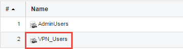
Before we start setting up the tunnel we need to add two objects in the cOS Core Address Book and add to the local user database.
First we will add a new Local User Database for our VPN users. Creating/adding a new local user database is done in the WebUI under System > Local User Database .
Once the database has been created it will look something like the example below:
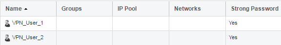
In this database we add the users that we want to use with our IKEv2 solution as shown below:
Now we need to create two IPv4 address objects. The first object will be the IP Pool from where the VPN clients will be assigned an IP and the second object is the DNS server that will be assigned to the connecting clients.

In this example we will use 192.168.1.10-192.168.1.20 for the pool, which means that the 192.168.1.0/24 network will be routed over the IKEv2 tunnel as explained earlier.
Note: One thing to consider is that the DNS requests are not going to be sent over the IKEv2, unless the DNS server is on the same subnet (192.168.1.0/24). One way to get around this is to assign the client a “Fake” DNS. For example, a core route IP in the same network range (192.168.1.0/24) and then use a SAT or NAT/SAT IP Policy in the firewall to forward the traffic to the correct DNS server.
An example IP Policy is shown below where the IKEv2 client will be assigned the core routed IP 192.168.1.1 as DNS server:

The Firewall Configuration
In this example we will use the VPN Clients (Simplified) object which simplifies roaming client setup. In order to create a VPN Clients object, go to Network > Interface and VPN > VPN and Tunnels > IPsec then click Add to add a new “VPN Clients (Simplified)”
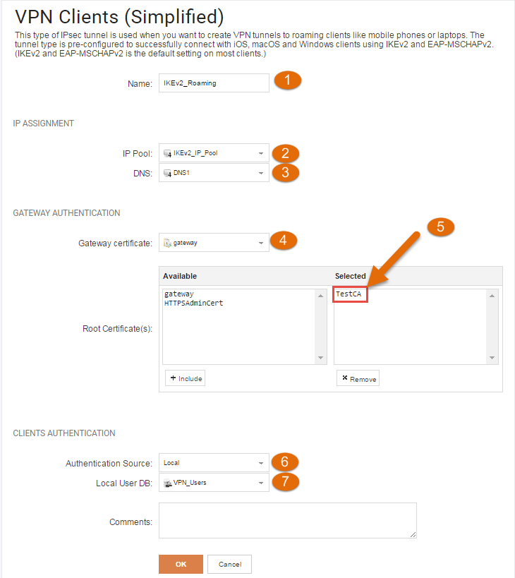
- Give your tunnel a suitable name.
2. Select the previously created IKEv2_IP_Pool . Clients connecting to the tunnel will be assigned an IP from this pool.
3. Specify a DNS to be handed out if required
4. Select your gateway certificate. As mentioned previously, this is explained further in https://kb.clavister.com/324736172/roaming-windows-ikev2-setup-with-netwall-as-ca-server
5. Select your Root certificate. This is explained further in https://kb.clavister.com/324736172/roaming-windows-ikev2-setup-with-netwall-as-ca-server
6. Set the authentication source to “Local”. You can also choose radius authentication if needed.
7. Select the local user DB with your VPN users, in our case “VPN_Users”.
The “VPN clients” object will create an EAP authentication rule in the background. One thing we need to do in order for this to work is to add a new route and proxy ARP the IKEv2_IP_Pool on the internal interface (GESW in this example).
To add a route go to Network > Routing > Static Routes > Routing Tables > main and click Add Route:
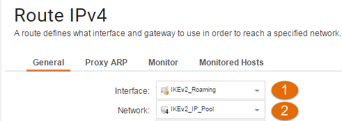
Note the following:
- The interface should be the IKEv2 tunnel.
2. Assign the network parameter the IKEv2_IP_Pool.
Under the Proxy ARP tab add the internal interface as shown below:
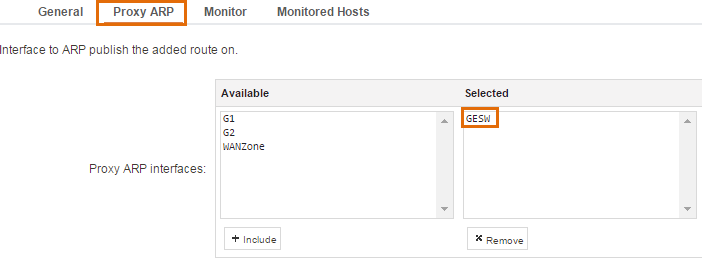
Important: We need to add this route in order for the clients on the inside to know where to send the return traffic. Since the VPN client(s) get an IP address in the same network range as existing servers/clients, the local clients/servers will believe the incoming request is part of their own local network and will start to perform ARP queries to find the MAC address. By enabling ProxyARP, the firewall will be the one that answers these requests and “pretends” to be the VPN client at a layer-2 level.
When clients connect, cOS Core will setup a single-host route for the IP that the client receives from the IP pool. However, since the Proxy ARP and the routes are using separate sub-processes, they are looked at separately. So even though the Proxy ARP route does not primary match (as it is bigger than the single-host route), it will still respond to the ARP query and the scenario will start to work.
IP Policies for the IKEv2 Roaming Tunnel
We only need one IP Policy since we have configured partial split tunneling and we only want to allow access to a specific internal network.

One thing to keep in mind here is that the IKEv2_IP_Pool is on the same /24 network as the internal_net so the IKEv2_IP_Pool IPs need to be reserved for the IKEv2 clients.
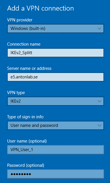
Configuring the Windows built-in VPN client
First, we need to create the new VPN connection as shown in the following image:
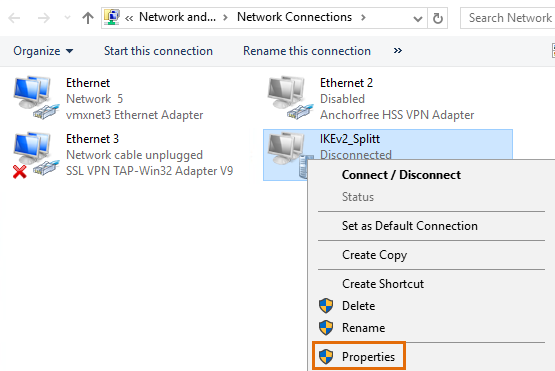
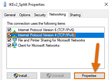
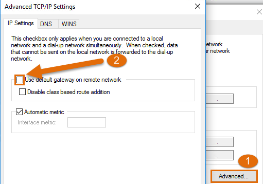
In order to achieve split tunneling, we need to disable “Use default gateway on remote network” on the VPN NIC. This option can be found under Properties > Networking > Properties if you right click on the NIC. If you don’t want to enable Split tunneling you can skip the rest of the steps.
Now we are done and the only traffic that should be routed over the IKEv2 tunnel is the 192.168.1.0/24 network. Everything else will use the normal internet route on the client.
Related articles
10 Mar, 2023 core vpn ikev2 windows radius certificate
9 Feb, 2024 core oneconnect windows splittunneling dns
16 Sep, 2020 vpn ipsec ikev2 windows howto dh
14 Mar, 2023 core ipsec vpn ikev2 certificate
22 May, 2024 netwall ikev2 windows certificate vpn core