Introduction
Imagine a scenario where a company is expanding and the need to create static routes for every single network is starting to become very difficult to manage manually. There is one way to solve this problem which is to run a dynamic routing protocol, a way to automatically distribute the routes. There are a couple of dynamic routing protocols out there for example EIGRP, OSPF and BGP just to mention a few of them but the one we’re setting up is OSPF. This guide will not explain OSPF in detail but it’ll give provide a basic understanding of when, why and how to configure it. Some terminology and explanation will be provided.
Generally, we can group these dynamic routing protocol into 2 groups, distance vector and link-state. OSPF is categorized as a link-state and EIGRP as a distance vector. To compare these two groups, imagine that you’re going on a road trip, a distance vector is more like following the signs toward the destination. Link-state is more like a GPS, you already got the full map and you simply chose the preferable route.
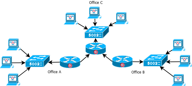
The image below illustrates a simple network topology where running a dynamic routing protocol might be preferable over static routes. In this scenario the users in Office A must be able to communicate with the users in Office B. There are 2 choices to make the communication possible and it’s either to summarize and create the routes from Office A to Office B through Office C or the use of a dynamic routing protocol. The second option, running a dynamic routing protocol requires an activation on all of the routers and what routes to distribute is up to the network administrator.
Terminology
EIGRP = Enhanced Interior Gateway Routing Protocol
OSPF = Open Shortest Path First
BGP = Borderless Gateway Protocol
LSA = Link state advertisement.
OSPF Database = Containing the LSA’s which includes routes, costs, network types and so on.
Hello packets = It’s a OSPF communication packet that is sent out periodically to establish and confirm adjacency between the routers. In broadcast / multicast environments it’s also used to discover neighbor routers. Per default it’s sent out every 10 second, this value can be changed.
Area = To keep it simple, an area is a sub-domain which means that if the routers are in the same area they keep the same OSPF database. Referring to Figure 1 this means that office B’s OSPF database will be identical to office A’s OSPF database meaning that they will contain the same routes. Area 0 is the backbone area and usually the first one to configure, for more advanced configurations area 0 can interconnect other areas.
DR / BDR / Drother = DR(Designated router) and BDR(Backup Designated Router). As mentioned the routers OSPF database must be identical if they belong to the same area, this means that there will be a lot of traffic on the links, to avoid this it exist a DR and one BDR per area. A drother is a router that is neither a DR or a BDR. So each drothers will exchange the OSPF database with only the DR. The BDR should be easy to understand, if the DR dies the BDR takes over.
RID(Router ID) = There is a value called RID which should be configured, based on that value the routers chose who will become DR or BDR. The highest RID will become the DR UNLESS a DR already have been elected. If for example the OSPF instance is running and a new router with a higher RID is added a new election process will not trigger, it won’t become the new DR unless the routers are rebooted or the OSPF process is restarted. The RID should be configured with 4 octets like an IP-address such as 1.1.1.1 or 2.2.2.2 (where 2.2.2.2 will become the DR).
Pros and cons
Running a dynamic routing protocol costs more resources to use compared to static routes. It’ll also be more CPU heavy and the more routes you add to the OSPF the more memory it’ll consume; one other downside is that it’ll use extra bandwidth when updating the OSPF database. The benefit is that if many routers is connected to each other there is no need to manually configure these routes everywhere, simply adding them to the OSPF process is enough. Another great benefit of running a dynamic routing protocol is that it scales well.
Components to configure
- Configure OSPF between two Firewalls using the main routing table.
- Configure IPsec tunnel using all-nets as remote and local network.
- Distribute routes with OSPF and route the traffic through the IPsec tunnel.
Configuring OSPF
1, First the topology needs to be defined, this will be a basic topology connecting only 2 firewalls with each other. Second a DR needs to be defined, in this scenario Firewall 2 will be the DR (normally the most centralized router / firewall should be preferred). A couple of objects need to be configured on both firewalls.
Firewall 1:
Backbone = 0.0.0.0
RID = 1.1.1.1
Firewall 2:
Backbone = 0.0.0.0
RID = 2.2.2.2
The area is not defined as a single 0 but as an octet, however 0.0.0.0 is area 0 in other words the backbone area.
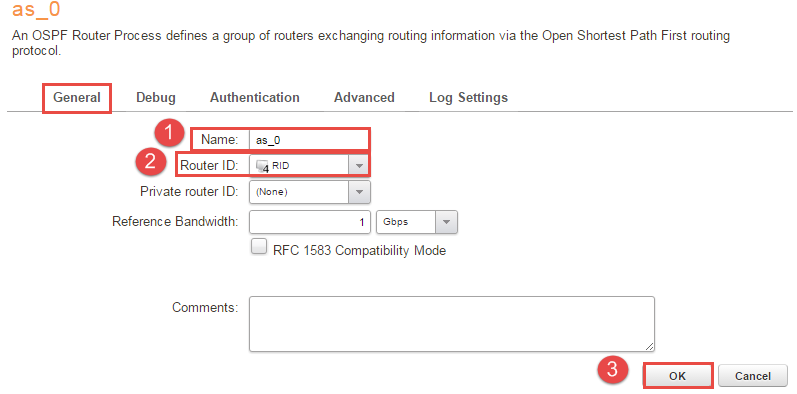
2, Under “Network -> Routing -> OSPF -> +Add -> OSPF Router Process” assign a name to it and add the object RID under “Router ID” as Figure 2 shows then press OK.
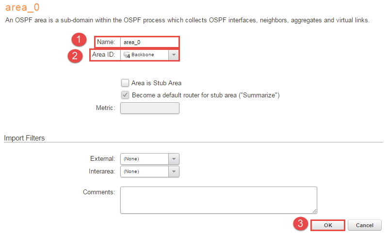
3, Under the newly created “as_0 -> +Add -> OSPF Area” and name it something convenient, in this case it’s called “area_0” and the Area ID should be the “Backbone” object that was created earlier. Look at Figure 3 for full configuration.
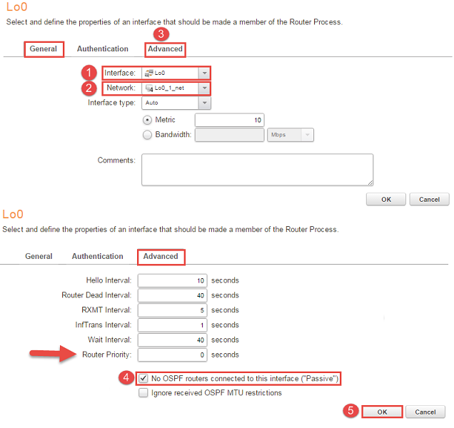
4, Under “area_0 -> OSPF Interfaces”, in this section two things will be added. First thing will be the networks that should be distributed to the other routers in area 0. To assign the address pool and interface go to “+Add -> OSPF interface” and add the interface / address pools. Go to the “Advanced tab” and check the box “No OSPF routers connected to this interface(“Passive”)”. The reasons why “No OSPF routers connected to this interface(“Passive”)” should to be checked is that if someone else connects a router it will not form convergence and the other reason is to decrease the CPU overhead. Figure 4 illustrates the configuration, please note that if the firewalls are in a cluster the router priority option MUST be changed to 0(An arrow in Figure 4 pointing towards it).
Additional note on “Passive” interface: adding an OSPF Interface and setting it to Passive is a quick way to “inject” a local network into OSPF process without using an Import Rule. It is valid only for directly connected networks. A Passive interface neither sends nor receives OSPF Hello packets, so no adjacency is established with OSPF speakers reachable from the passive interface: the firewall does not send and does not listen for incoming advertisement; OSPF process simply does not run on that interface.
For OSPF Broadcast interfaces, it is a good practice to set interface as Passive if no OSPF speakers are expected behind the interface, in order to avoid unnecessary OSPF traffic but also for security reasons: unwanted routes might be accepted by the firewall if a fake router is started in the network segment. For Point-to-Point and Point-to-Multipoint interfaces, this option is not applicable, since at least a OSPF speaker is expected behind the interface and OSPF Neighbors must be explicit.
5, After the networks that’s supposed to be redistributed to the other firewalls is added it’s time to configure the interface that connects the firewalls. Just configure it as with previous interfaces but leave the “No OSPF routers connected to this interface(“Passive”)” unchecked which will allow the firewalls to form convergence with each other.
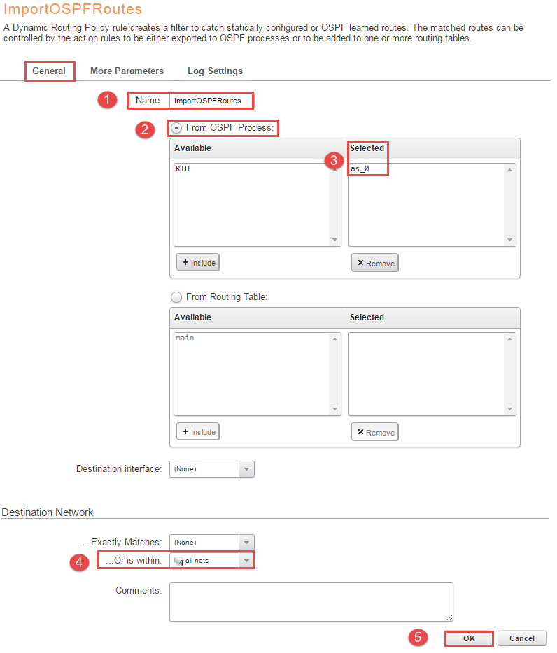
6, Next step is to import the routes from the AS into the routing table, in this scenario the main table will be used. Under “Network -> Routing -> Routing Rules -> + Add -> Dynamic Routing Policy Rule” name it something convenient, in this example the name is “ImportOSPFRoutes” and check “From OSPF process” and select “as_0”. Go to the “Destination Network” and select all-nets in “…Or is within:”. Figure 5 illustrates the configuration.
One reason to why at least one dynamic routing rule is needed is that the routing table might contain sensitive information, so to avoid that the routing database gets published or picking up faulty routes a dynamic routing rule is needed. This rule is used to import the OSPF routes into the local routing table. One export rule will be created under part 8 to export the routes to the OSPF AS from the main table.
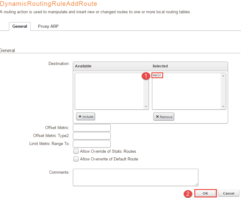
7, Under “ImportOSPFRoutes -> Routing Actions -> +Add - > DynamicRoutingRuleAddRoute” move “main” to the selected box and leave the rest of the values at their default, press OK. Figure 6 illustrates the configuration for clarification.
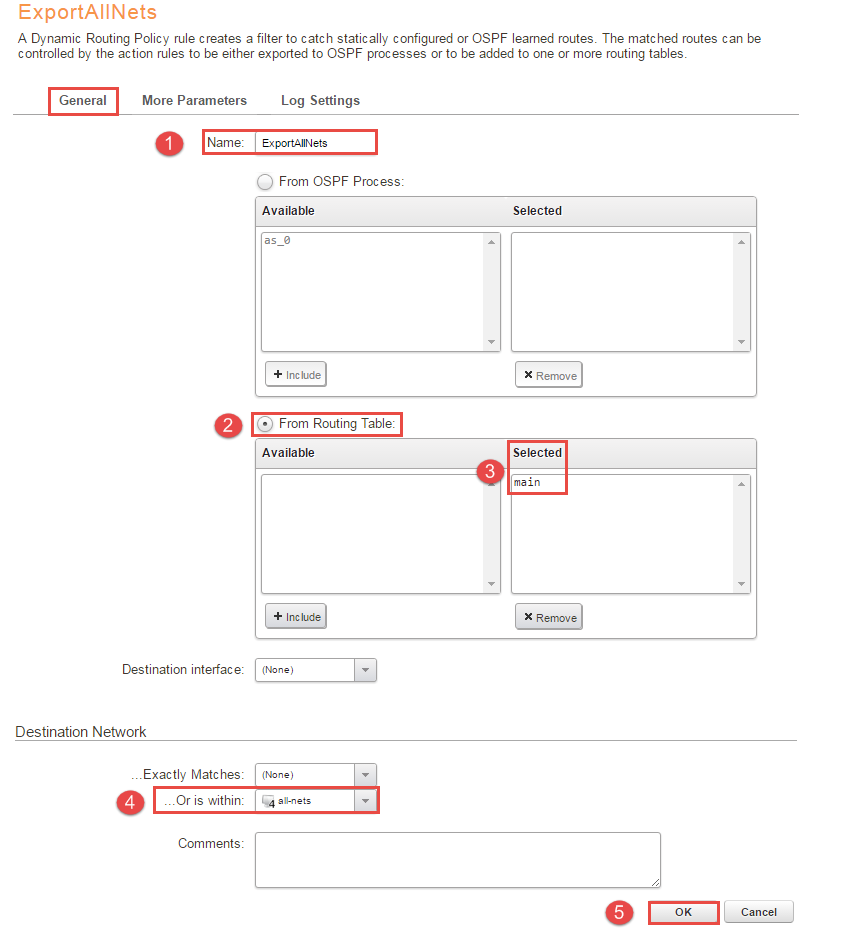
8, Next step is to export the routes to the OSPF process from the main table, under “Network -> Routing -> Routing Rules -> Add -> Dynamic Routing Policy Rule” choose a name, this example used “ExportAllNets”. Next mark the “From Routing Table” and include “main” into the box, once again select “all-nets” under “Destination Network -> …Or is within:” and press OK. Figure 7 will illustrate the configuration.
If a separated routing table is used containing only for example OSPF routes that table can be used instead. If configured under the exportrule that routing table will be injected into the OSPF AS instead of the main table.
One other note is the ability to filter the routes with the “…Or is within:” can be handy, it’s possible to specify if the network need to be within a specific network. In this scenario a “all-nets” network is being used which means that basically no filtering is being done. All of the networks defined in OSPF interfaces is being injected to the OSPF process.
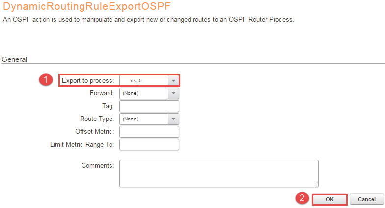
8, Select the “ExportAllNets -> OSPF Actions -> +Add -> DynamicRoutingRuleExportOSPF” under “Export to process” and add as_0 and press OK. Figure 8 will illustrate the configuration.
9, Save and activate and do the same configuration on the other firewall/router and they should reach convergence. The following CLI commands will help you to verify the settings below.
Before moving on to the next step please make sure that the OSPF process is up and running, see the troubleshooting section at the end for more information.
LAN-to-LAN IPsec tunnel
It’s time to configure the IPsec tunnel, the configuration pasted below can be used, for more detailed discussion about IPsec please look into the administration guide or other forum posts. This tunnel will not have any routing configured on it directly so even though this is a all-nets tunnel it shouldn’t cause any routing problems, OSPF will handle the routing. There are a couple of objects needed not only for the tunnel but for OSPF also, please add these and then configure the tunnel as below, this should be configured on both of the firewalls. Leave all values not mentioned at default.
Do NOT use auto establish on this tunnel, OSPF will keep the tunnel open with the “hello” packets every 10 second by default (this value can be changed). Auto establish is aggressive and will create more SA’s than needed, the license allows only a limited amount of tunnels so the configuration should be as efficient as possible.
Firewall 1:
Remote_gw = IP address of the remote endpoint of firewall 2
OSPF_PSK = Pre shared key for the IPsec tunnel, should match the other side
IPsec_INT = 192.168.50.1 (can be anything, OSPF specific though will be used more later)
OSPF_Neighbor = 192.168.50.2 (Will be used under the topic OSPF in a tunnel) ; This should match the firewall 2 IPsec_INT
OSPF_Tunnel_net = 192.168.50.0/24 (Will be used under the topic OSPF in a tunnel, this can be a /31 link net)
Firewall 2:
Remote_gw = IP address of the remote endpoint of firewall 1
OSPF_PSK = Pre shared key for the IPsec tunnel, should match the other side
IPsec_INT = 192.168.50.2 (can be anything, OSPF specific though will be used more later)
OSPF_Neighbor = 192.168.50.1 (Will be used under the topic OSPF in a tunnel); This should match the firewall 1 IPsec_INT
OSPF_Tunnel_net = 192.168.50.0/24 (Will be used under the topic OSPF in a tunnel, this can be a /31 link net)
Tunnel configuration
Go to “Network -> IPsec -> +Add -> IPsec tunnel” and configure as below, the rest of the values should be left at default. Configure this on both of the firewalls.
General Tab
Name = OSPF_LAN
Local network = all-nets
Remote Network = all-nets
Local Endpoint = (None)
Source Interface = any
Remote Endpoint = remote_gw
Outgoing Routing Table = <main>
Encapsulation mode = Tunnel
IKE Config Mode Pool = (None)
IKE Algorithms = High (default)
IKE Lifetime = 28800 (any value higher than 3900) s
IPsec Algorithm = High (default)
IPsec Lifetime = 3600 s
IPsec Lifetime = 0 kB
Authentication tab
Select OSPF_PSK
Advanced tab
Disable “Add route dynamically”
Disable “Add route statically”
Specify address manually = IPsec_INT (will be explained in the next section)
OSPF in a VPN tunnel
With the OSPF and the IPsec tunnel up and running there are a couple of things that needs to be changed and added in order for it to work properly together. Normally when OSPF sends the “hello” packets over the network it’s using multicast address 224.0.0.5 or 224.0.0.6. This creates a problem, the IPsec tunnel does not support multicast completely(multicast traffic will enter the tunnel but the receiver will not accept them) so the firewalls will not be able to form convergence. There are two ways of solving this, the multicast can either be transported using a GRE tunnel or statically configured the adjacency. This guide will cover how to manually configure the adjacency and turning off the multicast resulting in that the conversation between the firewalls will be done with unicast.
As mentioned in the “Tunnel Configuration” the “IPsec_INT” object was added to the tunnel interfaces, this will be used as a identifier. With the identifier configured there must be some way for the OSPF process to know who to talk to, there is a setting in the OSPF process “OSPF neighbor” that will do just that.
The tunnel can either be configured as point-to-point or point-to-multipoint but the advantage of using point-to-multipoint is that it turns off the multicast traffic over the tunnel resulting in that the conversation between the firewalls will be done only with unicast. Another advantage to use point-to-multipoint is that multicast and broadcast will be deactivated so the object “OSPF_Tunnel_net” can be a /31 link net, saving some addresses.
Start the configuration and the changes on Firewall 1
- Go to “Network -> Routing -> OSPF -> as_0 -> area_0 -> OSPF Neighbors -> +Add -> OSPF neighbor”. Under interface choose “OSPF_LAN” and IP-address “OSPF_Neighbor” and press OK. This is the place that defines where the OSPF neighbors is, the other firewalls.
- Go to “Network -> Routing -> OSPF -> as_0 -> area_0 -> OSPF Interfaces” and disable the interface connecting to the other firewall. The convergence will be lost. As mentioned OSPF is supposed to use the IPsec tunnel so it should not advertise the routes over the external interface towards the open internet.
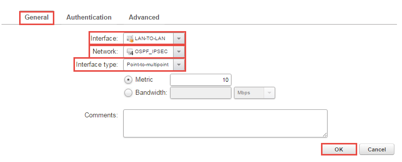
- Press “+Add -> OSPF Interface” and under interface pick “OSPF_LAN” and network “OSPF_Tunnel_net”, change the interface type to “Point-to-multipoint”, look on Figure 9 for clarification. Do note that if you’re running a HA change “Router Priority:” to 0 under advanced. Now the multicast will be turned off and the firewalls sends "hello" packets using unicast.
- Do the same configuration on firewall 2.
Alternative solution
Instead of using the “Main” routing table a cleaner solution would be to use a separate routing table that include the routes that the firewall should redistribute to the other firewalls. The benefit of doing this is that the routing will be easier to manage and control.
Related articles
11 Jan, 2023 ipsec core vpn
24 Mar, 2023 core ipsec ippool dhcp
21 Oct, 2022 core arp routing
12 Apr, 2023 core proxyarp arp ipsec routing
28 Mar, 2023 ikev2 windows vpn routing splittunneling
18 Mar, 2024 core certificate oneconnect ipsec vpn
2 Jul, 2026 vpn core ipsec alg highavailability trafficshaping
23 Nov, 2022 core ipsec
21 Feb, 2023 ipsec certificate windows ca core
22 Mar, 2021 core ipsec routing
18 Mar, 2024 core incontrol certificate oneconnect ipsec vpn
17 Jun, 2021 core ipsec routing
30 Nov, 2022 core routing
1 Jun, 2022 core routing management
8 Mar, 2023 core l2tp ipsec
20 Feb, 2023 core vpn ipsec
25 Nov, 2022 core routing bgp
4 Aug, 2023 core ipsec troubleshoot ike
14 Apr, 2021 core license ipsec
8 Sep, 2020 core ipsec rules access
29 Mar, 2023 ipsec core windows vpn l2tp
25 Sep, 2025 core routing pbr
5 Apr, 2023 ipsec core
16 Sep, 2020 vpn ipsec ikev2 windows howto dh
7 Dec, 2022 ipsec ike troubleshoot core
14 Dec, 2022 core ipsec
16 Oct, 2023 howto core pbr routing netwall isp
5 Apr, 2023 core nps ipsec radius legacy
15 Dec, 2022 core routing ospf
14 Mar, 2023 core ipsec vpn ikev2 certificate
12 Jan, 2026 core howto routing redundancy
23 Aug, 2022 core ipsec license memory
7 Nov, 2022 core arp log routing
15 Mar, 2023 core ipsec ipv6
6 Apr, 2023 core ripv2 routing
17 Mar, 2023 core routing rules ping icmp cli
23 Aug, 2022 core connections ipsec memory
27 Jan, 2021 core stateless routing brokenlink
13 Feb, 2023 ipsec core routing failover
18 Apr, 2023 core routing transparentmode proxyarp
28 Mar, 2023 dhcp ipsec core