Intro
This guide will go through an example on how to setup a Lan to Lan IPsec tunnel between two devices/endpoints.
Note-1: Some of the screenshots are from an older version of cOS Core and may look different in newer versions but the general principle is still the same.
Note-2: Ciphers and encryption algorithms and recommendations change over time. In one of the screenshots in this article SHA-1 is used, this is no longer recommended and at the time of this update, SHA-256 is the minimum recommended Integrity algorithm but that will most likely change in the future as well. This guide is an example on how to set up an Lan to Lan tunnel.
Note-3: The VPN cookbook also discusses in great detail on how to setup a Lan to Lan tunnel, using this guide or the book will be up to the reader. The VPN cookbook can be freely downloaded from here (as PDF) : https://www.clavister.com/services/resources/configuration-cookbooks/
Pre-requisities
Two Clavister cOS Core firewalls or one Clavister cOS Core firewall and another type/brand of VPN terminator.
Note: As long as the remote endpoint device follows the IPsec standards it will be possible to setup a Lan2Lan tunnel between Clavister and whatever device used as the remote endpoint.
All the following configuration steps should be repeated on both firewalls/endpoints.
Preparing the Address Book
The first thing to do is to add all objects needed by the IPsec tunnel. The remote network and the remote gateway. When this is done, we should have two new objects in the address book. Remember that we need to do a similar configuration on your second firewall.
Note: All these addresses are examples.
First firewall:
Remote_network = 192.168.40.0/24
Remote_endpoint = 172.16.12.2
Second firewall (or device):
Remote_network = 192.168.30.0/24
Remote_endpoint = 172.16.12.1
It should look something like this in the WebUI
Creating the Pre-Shared Key
To be able to authenticate the IPsec tunnel that will be used, a pre-shared key needs to be created. A pre-shared key can either a passphrase or a randomly generated Hexadecimal key. This is done under Objects > Key Ring > Add Pre-Shared Keys.
Note: You need to define the same PSK on the second firewall.
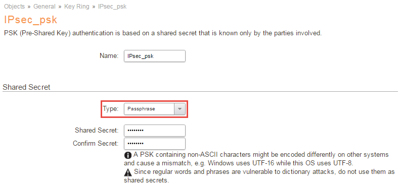
In this Guide we will use a PSK called: IPsec_psk.
Create custom IKE and IPsec Proposal lists (optional)
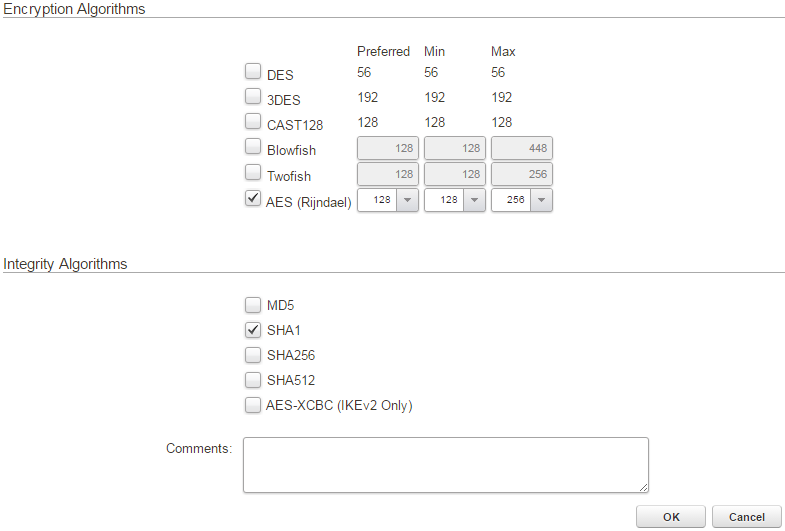
This optional step is needed if you either want to use specific encryption and integrity algorithms or if the other end uses specific settings that you must match and the predefined proposal lists (Medium and High) does not work.
In this how-to we will create new algorithms for our IPsec tunnel.
Create two proposal lists, one for IKE and one for IPsec. Select SHA1 and AES as algorithms and name them accordingly.
This is done under Objects > VPN Objects > IKE/IPsec Algorithms section:
Create the IPsec Tunnel 
Now it’s time to set up the IPsec tunnel, this is done in the IPsec Tunnels section located in the Network tab of the Clavister firewall.
Settings & options on the IPsec tunnel
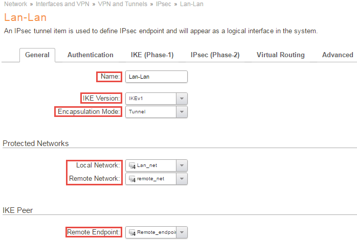
Name
First of all, a name is needed for the VPN connection.
In this example, the name Lan-Lan is being used.
IKE Version
Here we select IKEv1.
Note: It is recommended to use IKEv2 whenever possible. If both endpoints support IKEv2, only this option needs to be changed on both sides in order to move from IKEv1 to IKEv2.
Encapsulation mode
As we are setting up a lan-lan tunnel this should be set to Tunnel Mode.
Local Network
This is the local network that the remote users will connect to and the local users connect from.
Usually this is “lan_net” or similar. It can also be a collection (group) of networks or ranges, or just a single IP. It can also be “all nets”.
The important thing is that this matches what is specified as “remote network” for the other Security Gateway.
We will use the Lan_net.
Note-1: This is the so called “remote_net” of the second gateway.
Remote Network
This is the network that the remote users will connect from or our local users connect to.
Here we select our earlier created “remote_net” object.
Remote Endpoint
This is the IPv4 Address of the firewall (or device) where the tunnel will be terminated (established to).
In this guide we select our created “Remote_endpoint“
Authentication
.png)
Authentication Method
Here we select our previously created PSK, “IPsec_psk”.
IKE(Phase-1) 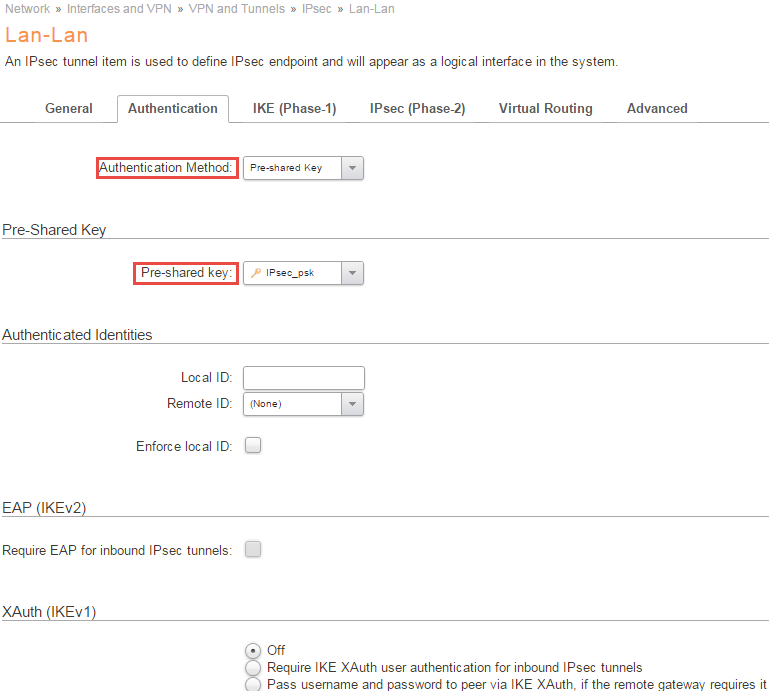
Diffie-Hellman group
Here we can leave the default value of 02(1024), simply remember to select the same DH-group on your second gateway.
Note: Similar as mentioned before, DH group 02 is no longer considered secure, at the time of this update the minimum recommended DH group is 15 and will change in the future as well. Make sure your selected ciphers is up to date with current recommendations.
Algorithms
Here we select the IKE algorithm we have determined to use with the other Security Gateway. Either use the predefined Medium or High, which contains several different algorithms and key lengths, but that will give you less control over the encryption methods used, so in this example we will use the specified algorithm we created earlier (AES, SHA1).
We leave the life-time to it’s default value.
Note: Similar as mentioned before, SHA-1 no longer considered secure, at the time of this update the minimum recommended integrity algorithm is SHA-256 and will change in the future as well. Make sure your selected ciphers is up to date with current recommendations.
Mode
We choose Main Mode and not aggressive mode since we want the connection establishment to be encrypted.
Note: Aggressive mode does not exist in IKEv2 and if possible, aggressive mode should never be used in IKEv1 either due to known exploits.
Outgoing Routing Table
We select the routing table main.
Local Endpoint
Here we select our DMZ_ip.
Note: This IP is the Remote_endpoint of the second gateway. Remember this interface IP is simply an example, you should use the interface and ip corresponding to your network.
Incoming Interface Filter
This is an optional setting used with virtual routing scenarios, so we will use the standard any.
Miscellaneous
Here we leave all settings to their default value.
IPsec(Phase-2)
.png)
PFS (Perfect Forward Secrecy)
We leave the default values.
Algoritms
Select the IPsec algorithm we created earlier and leave the life-time settings to there default.
Setup SA Per
Leave it at default Network.
Advanced 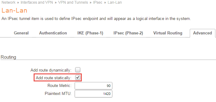
Routing
Under the routing section under advanced make sure that you have Add Route Statically selected.
IP Policies
When configuring a two-way tunnel, two IP Policies are needed. One IP Policy to allow traffic coming from the remote network to the local network and another IP Policy to allow traffic to go from the local network through the tunnel to the remote network. If you want to limit to a single direction, or that only a specific IP, e.g. a web server, or port/protocol should be allowed, you can adjust your IP policies accordingly.
Outgoing traffic
Action is Allow, Source Interface is Lan, Source Network is Lan_net, the Destination Interface is Lan-Lan, the Destination Network is Remote_net and Service is All_Services (We might want to use a different Service to limit the allowed traffic).
Incoming traffic
Action is Allow, Source Interface is Lan-Lan, Source Network is Remote_net, the Destination Interface is Lan, the Destination Network is Lan_net and Service is All_Services (We might want to use a different Service to limit the allowed traffic).
When done with the IP Policies it will look something like this:

Note: Remember to do matching settings on the other Firewall or device.
For trouble shooting, we recommend that you connect to the CLI and use the “ikesnoop -on -verbose” command to see the tunnel negotiation. Since Keep Alive was not activated in this example, an easy method to establish the tunnel is to ping any host address in the remote_net. The response itself is not the primary goal here, just to start up the tunnel, so it does not matter if a host is there or not. Also see the following KB about troubleshooting IPsec tunnels : https://kb.clavister.com/324736401/troubleshooting-ipsec-tunnels-ikev1-
You can also ping simulate incoming and outgoing traffic, to verify your IP Rules and routing.
Outgoing
Assuming 192.168.40.0/24 is the remote_net and 192.168.30.0/24 is Lan_net. Again, neither host need to actually be there and respond, although it is more fun if they do, the goal is to verify the route and IP Rules used
ping 192.168.40.5 -srcif=lan -srcip=192.168.30.2 -verbose
Incoming
ping 192.168.30.2 -srcif=Lan-Lan -srcip=192.168.40.5 -verbose
For more details about ping simulations, please see the Appendix-A in the VPN cookbook.
Related articles
11 Jan, 2023 ipsec core vpn
10 Mar, 2023 core vpn ikev2 windows radius certificate
24 Mar, 2023 core ipsec ippool dhcp
12 Apr, 2023 core proxyarp arp ipsec routing
28 Mar, 2023 ikev2 windows vpn routing splittunneling
18 Mar, 2024 core certificate oneconnect ipsec vpn
23 Nov, 2022 core ipsec
21 Feb, 2023 ipsec certificate windows ca core
22 Mar, 2021 core ipsec routing
18 Mar, 2024 core incontrol certificate oneconnect ipsec vpn
11 Dec, 2025 core routing ospf ipsec
17 Jun, 2021 core ipsec routing
8 Mar, 2023 core l2tp ipsec
4 Aug, 2023 core ipsec troubleshoot ike
14 Apr, 2021 core license ipsec
8 Sep, 2020 core ipsec rules access
29 Mar, 2023 ipsec core windows vpn l2tp
5 Apr, 2023 ipsec core
16 Sep, 2020 vpn ipsec ikev2 windows howto dh
7 Dec, 2022 ipsec ike troubleshoot core
14 Dec, 2022 core ipsec
5 Apr, 2023 core nps ipsec radius legacy
14 Mar, 2023 core ipsec vpn ikev2 certificate
23 Aug, 2022 core ipsec license memory
15 Mar, 2023 core ipsec ipv6
22 May, 2024 netwall ikev2 windows certificate vpn core
23 Aug, 2022 core connections ipsec memory
13 Feb, 2023 ipsec core routing failover
28 Mar, 2023 dhcp ipsec core