Introduction
Pipes are an excellent feature for creating priorities for different kinds of traffic and limit the top speed of certain types of traffic. A common scenario is to implement traffic prioritization and load distribution to stop one particular client or server to allocate all available bandwidth.
Pipes can either be used the “classic” way, by using Pipe Rules, but it can also be used in conjunction with Intrusion Detection and Prevention (IDP) and Application Control (AppCtrl). This guide will handle the Pipe Rules method.
Pipe Rules
When using Pipe Rules, the traffic is recognized by source interface, source address, destination interface, destination address and service, for mapping that traffic into a certain pipe or chain of pipes on a certain precedence (=priority) level.
Pipe limits and precedence levels
Precedence levels are the priority levels used in a Quality of Service (QoS) scenario. Precedence 0 is the lowest and where all left-over traffic ends up. This is known as “best effort”. Precedence 7 is the highest priority level, and traffic here will get service before all the underlying levels.
If there is more traffic in a given precedence level than what is guaranteed at that level, then the excess traffic is forced down to precedence level 0, where it has to compete for any remaining capacity. This means that traffic at underlying levels will have a chance to get service, even if a large amount of high priority type of traffic exists.
In the Total field of the Pipe Limits tab, the maximum amount of traffic the pipe can send (kbps) is entered. This value can not be overridden by the values entered at the precedence levels; if Total=1000, it is useless to enter Precedence 7=2000, since 1000 is the maximum.
When defining a pipe, three precendence values can be entered: Minimum, Default and Maximum. They define the available levels and what the default value is, which can be utilized in the Pipe Rules with the setting Use defaults from first pipe. It means that the traffic matching that Pipe Rule will use the precendence level defined by the Default value.
From now on, Precedence 0 to 7 is typed as P0 to P7.
ToS (IP DSCP)
There are 8 Precedence levels, which matches the 3 bit field in the IP header describing different traffic priorities. The Map IP DSCP (ToS) field will map each IP packet to its respective precedence level.
Pipe chaining
Pipe chaining means that two or more pipes are connected end to end, so traffic first flows through one pipe, and then it flows through the following pipe, etc.
This can be used to shape the traffic in many ways, for example to move traffic to another precedence level, to limit the total amount of this type of traffic and so on.
There are no “sanity checks” on pipe chaining, so very strange scenarios can easily be created, e.g. sending a flow of traffic several times through the same pipe, or mixing inbound and outbound traffic in the same pipe. It is completely up to the administrator to understand how pipes work and utilize them in a way that makes sense.
Grouping & Dynamic balancing
Grouping in conjunction with dynamic balancing is used for fairness between the different users/applications that use the pipes at any given moment. It avoids the problem of one user taking all traffic in a precedence level, leaving nothing for the other users, so their traffic will be forced down to P0 even though they should be qualified for a higher Precedence level, or they will even be facing starvation where they will get no service at all for a long period of time.
The fairness will, simplified, be a calculation on how many concurrent users there are, and divide the available bandwidth equally between them.
For the Clavister Security Gateway to know how to perform the fairness calculation, the Grouping feature is used. It has values such as Per DestNet, Per DestIP, Per DestPort and so on. Normally the in-pipe is grouped Per DestIP and the out-pipe is grouped Per SrcIP.
Testing a Pipes configuration
When testing pipes a very useful tool to use is IPerf which can be used to generate traffic from A to B with the type and amount of data we want. When testing pipes this can be very useful. For more information about IPerf see https://iperf.fr/.
Example 1 - A basic scenario
This first simple example will limit all traffic, incoming and outgoing, to 1 Mbps using two pipes.

The reason we’re using two separate pipes, is that it is the only way to match to the physical capacity on the external link, as it can be viewed as two separate links, one inbound and one outbound. Our pipes will be setup to match them and if the link has different speeds such as a 8/0.5 Mbps ADSL, then we just match those values on our in and out pipes.
Pipes
First, create two pipes, one for incoming and one for outgoing traffic. Set a Total limit of 1000 on the Pipe Limits tab. Enable Grouping on IP (as we have only a single local network, lan_net, and we want to balance per PC on that network) with Dynamic balancing.
Name=In-Pipe, Total=1000 kbps, Grouping=Destination IP, Dynamic Balancing=on
Name=Out-Pipe, Total=1000 kbps, Grouping=Source IP, Dynamic Balancing=on
Note: In all examples of pipes, we will be using Bits Per Second and never Packets Per Second.
Pipe Rule
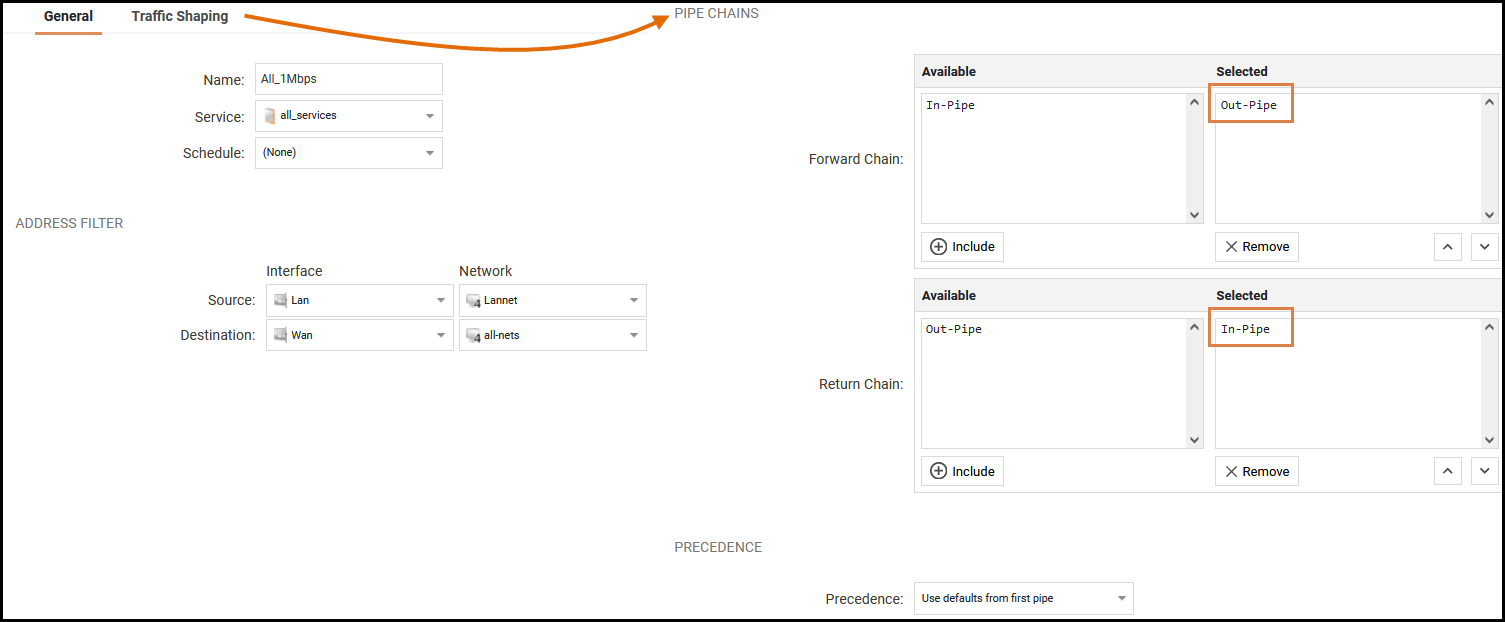
Create a Pipe Rule using the pipes. This rule will use the default precedence level (P0) and by the use of pipes, limit all traffic to 1 Mbps, but with Dynamic Balancing enabled, so each of our users will get a fair amount of the 1 Mbps capacity.
The users are located on the lan interface on the lan_net (192.168.1.0/24), and we are limiting their connection to the wan interface to all-nets.
Name=All_1Mbps, SrcIf=lan, SrcNet=lan_net, DestIf=wan, DestNet=all-nets, Service=All_services, Forward pipes=Out-Pipe, Return pipes=In-Pipe
After deploying this configuration, it’s time to test the pipe setup. Either simply try to surf and download files from a website, use an online speed-test site, or use the IPerf tool.
Example 2 - Using precedence levels
In this example, we’ll use several different precedence levels, one each for VoIP, Citrix, Other and Web surfing, where Web surfing has the lowest priority (P0) which it shares with eventual traffic of the other kinds, not fitting in their respective precedence level.
It can be wise to separate the levels used if we later wants to insert a new kind of traffic between two others.
This is the scenario for our headquarters. They have a 2/2 Mbps (symmetric) link to the Internet.
P6: VoIP 500 kbps
P4: Citrix 250 kbps
P2: Other traffic 1000 kbps
P0: Web + remaining from the other P-levels
We can continue from our previous example and modify the in-pipe and the out-pipe, plus modify and create a few new rules that force the traffic into their respective precedence levels.
In the Pipe Limits tab for both pipes (we’re reserving the same amount in both directions in this example), we enter:
P6: 500
P4: 250
P2: 1000
Total: 2000
Create the needed services (VoIP uses H323 in this example, which exists as a pre-defined service), Citrix uses Port 1494.
Now we create the pipe rules. Remember that the rules are read top-to-bottom, hence the WebSurfing rule must be above the Other (All services) rule, or it won’t have a chance to trigger.
Also remember that for traffic shaping to work well, no traffic can bypass the pipes, or it will render the traffic shaping effort useless. The reson is the greedy behaviour of TCP/IP: “I will take everything I can”.
| Index | Name | Forward Pipes | Return Pipes | Src Iface | Src Net | Dest Iface | Dest Net | Service | Precedence |
|---|---|---|---|---|---|---|---|---|---|
| 1 | WebSurf | Out-Pipe | In-Pipe | Lan | Lannet | Wan | All-nets | Http-All | Use Fixed: 0 |
| 2 | VoIP | Out-Pipe | In-Pipe | Lan | Lannet | Wan | All-nets | H323 | Use Fixed: 6 |
| 3 | Citrix | Out-Pipe | In-Pipe | Lan | Lannet | Wan | All-nets | Citrix | Use Fixed: 4 |
| 4 | Other | Out-Pipe | In-Pipe | Lan | Lannet | Wan | All-nets | All | Use Fixed: 2 |
Now it’s time to verify this setup, but it will be left as an exercise for the reader.
Example 3 - Using pipe chaining
Now let’s modify the example above to have several pipes in a chain. What we want to achieve is that the P2 (Other traffic) is restricted to 1000 kbps (ie. not allowed to “spill over” traffic to P0).
This is done by using pipe chaining, where we introduce a pipe with a Total limit of 1000 kbps and we modify the Other rule to use both the in-pipe and the in-other pipe in series for the inbound traffic, and the out-pipe and the out-other pipe in series for the outgoing traffic.
Create an in-other pipe and an out-other pipe and in the Pipe Limits tab for both pipes (we’re reserving the same amount in both directions in this example), limit to 1000 kbps. We need not activate Grouping or Dynamic balancing, as that is handled in the in- and out-pipes.
Name=In-Other, Total=1000 kbps
Name=In-Other, Total=1000 kbps
Now, we modify the Other pipe rule to use both pipes.
Take special note that the in-other and out-other pipes are first in the pipe chain in both directions. That’s because we want to limit the traffic immediately, before it enters the in-pipe and the out-pipe, where it competes with the VoIP, Citrix and WebSurfing traffic!
| Index | Name | Forward Pipes | Return Pipes | Src Iface | Src Net | Dest Iface | Dest Net | Service | Precedence |
|---|---|---|---|---|---|---|---|---|---|
| 1 | Other | Out-Other, Out-Pipe | In-Other, In-Pipe | Lan | Lannet | Wan | All-nets | All | Use Fixed: 2 |
Example 4 - Using pipes with IPsec VPN
In the examples above, we’ve been shaping traffic initiated from the inside of a single Clavister firewall. In many cases the entire setup includes a headquarters and one or several branch offices, connected via VPN. In these cases, we need to create rules in the opposite direction as well, using the IPSec interface (VPN tunnel) as source respective destination.
When using VPN tunnels, we need to adapt the Total value of the pipes to allow the VPN overhead to pass through the physical pipe. A bit of experimenting might be useful, but on a 2 Mbps link, a Total value of about 1700 is reasonable.
Note: Remember to insert all non-VPN traffic into the pipes as well, or the pipe setup won’t work very well.
To achieve a good solution to the VPN overhead problem, pipe chaining is a good choice. We’ll limit the traffic we insert into the VPN tunnel, allowing for the overhead, and all other traffic is inserted straight into the pipe that matches the speed of the physical link:
In the following example, we’ll create separate pipes for the upload traffic and for the download traffic. We’ll have VoIP via VPN with higher priority and all other traffic as best effort (We’ll assuming a 2/2 Mbps symmetric link. We need to set the same guaranteed limit on both pipes, or the guarantee will be “lost” in the in- and out-pipes:
VPN-in
P6: VoIP 500 kbps
P0: Best Effort
Total: 1700
VPN-out
P6: VoIP 500 kbps
P0: Best Effort
Total: 1700
In-Pipe
P6: VoIP 500 kbps
Total: 2000
Out-Pipe
P6: VoIP 500 kbps
Total: 2000
Now it’s time to create the rules needed to force all traffic into the correct pipes and precedence levels:
| Index | Name | Forward Pipes | Return Pipes | Src Iface | Src Net | Dest Iface | Dest Net | Service | Precedence |
|---|---|---|---|---|---|---|---|---|---|
| 1 | VPN_VoIP_out | VPN-Out, Out-Pipe | VPN-in, In-Pipe | Lan | Lannet | VPN | VPN_Remote_Net | H323 | Use Fixed: 6 |
| 2 | VPN_out | VPN-Out, Out-Pipe | VPN-in, In-Pipe | Lan | Lannet | VPN | VPN_Remote_Net | All_Services | Use Fixed: 0 |
| 3 | VPN_VoIP_in | VPN-in, In-Pipe | VPN-Out, Out-Pipe | VPN | VPN_Remote_Net | Lan | Lannet | H323 | Use Fixed: 6 |
| 4 | VPN_in | VPN-in, In-Pipe | VPN-Out, Out-Pipe | VPN | VPN_Remote_Net | Lan | Lannet | All_Services | Use Fixed: 0 |
| 5 | Out | Out-Pipe | In-Pipe | Lan | Lannet | Wan | All-nets | All_Services | Use Fixed: 0 |
| 6 | In | In-Pipe | Out-Pipe | Wan | All-nets | Lan | Lannet | All_Services | Use Fixed: 0 |
Now all VPN traffic is limited to 1700 kbps, the total traffic is limited to 2000 kbps and VoIP to the remote site is guaranteed 500 kbps before it is forced to best effort mode.
Example 5 - Using pipes with SAT address translation
If we are performing destination address translation (for example, SAT) for traffic (this might be for a web server or ftp server etc. located behind the firewall), we need to force that traffic too into pipes, or it will go “outside” of our pipes, and will most likely ruin our QoS setup.
We also need to reverse the order of the pipes: as forward pipe is our in-pipe, as return pipe is our out-pipe, due to the fact that the traffic is initiated from the outside (Internet).
A simple method to solve this is to create a catch-all-inbound rule at the bottom of our pipe rule list, but select the external interface (Wan) as source, to avoid traffic from the inside to our external IP being put into the pipes:
| Index | Name | Forward Pipes | Return Pipes | Src Iface | Src Net | Dest Iface | Dest Net | Service | Precedence |
|---|---|---|---|---|---|---|---|---|---|
| 7 | All_Incoming | In-Pipe | Out-Pipe | Wan | All-nets | Core | All-nets | All_Services | Use Fixed: 0 |
Note: If our SAT is from a ARPed IP (instead of an interface IP or manual Core route), we need to set the WAN interface as destination instead of Core.
Related articles
2 Jul, 2026 vpn core ipsec alg highavailability trafficshaping
6 Feb, 2023 core trafficshaping pipes tcp