Scenario 1 - Two ISP’s at only one side
A firewall with one ISP (Internet Service Provider) has an IPsec tunnel towards a firewall with two ISP’s.
We want to be able to use the Route Failover feature on the firewall with two ISP’s. If the primary ISP/Route goes down it should be able to establish the IPsec tunnel using the secondary/backup ISP.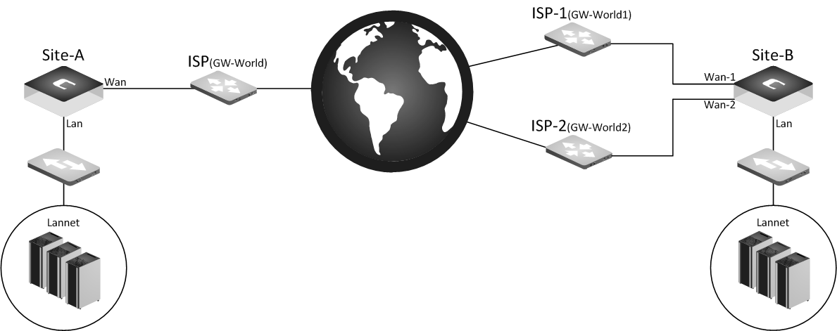
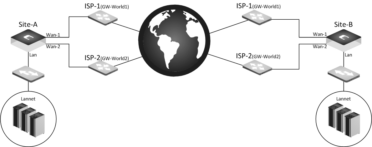
Scenario 2 -Two ISP’s at both sides
A firewall with two ISP’s has an IPsec tunnel towards a firewall which also has two ISP’s.
A bit more complex but with more redundancy, if any of the primary ISP’s on either side goes down it should establish and use the backup IPsec tunnel.
Solution - Scenario-1
Since we do not have two ISPs on both sides, there is no need to use two IPsec tunnels. We simply setup the RFO (Route Failover) towards the ISP only and then configure the IPsec tunnel to accept this. It is possible to use two IPsec tunnels in this scenario but it will only add another layer of complexity that is not really needed.
Base configuration
Site-A (One ISP)
Lannet=10.10.10.0/24
Wannet=80.80.80.0/24
IP_Wan=80.80.80.10
Routing Table(Site-A)
Route Lan Lannet
Route Wan Wannet
Route IPSecTunnel SiteBLannet
Route Wan All-nets Gw-World
Site-B (Two ISP’s)
Lannet=192.168.200.0/24
Wannet=90.90.90.0/24
Wannet2=100.100.100.0/24
IP_Wan=90.90.90.10
IP_Wan2=100.100.100.10
Routing Table(Site-B)
Route Lan Lannet
Route Wan Wannet
Route Wan2 Wannet2
Route IPSecTunnel SiteALannet
Route Wan All-nets Gw-World
Route Wan2 All-nets Gw-World2
The routing table on Site-B is, in its current state, incorrect. The reason is that because we have two “identical” routes on the all-nets route. Without a metric definition the firewall will be unable to determine which ISP it should use for different traffic, for example HTTP traffic. Sometimes you may use Wan and sometimes Wan2, so this is not a good setup for the moment.
Since we want to have redundancy we first need to setup the RFO, in this particular scenario it is fairly simple. We edit the routing table on Site-B to look like this.
Updated configuration / routing
Route Lan Lannet
Route Wan Wannet
Route Wan2 Wannet2
Route IPSecTunnel SiteALannet
Route Wan All-nets Gw-World Metric=10 Monitor=Yes
Route Wan2 All-nets Gw-World2 Metric=20
What to choose to monitor here is up to the administrator, it can be ARP, Link and/or HostMonitor depending on the requirement and needs.
Note: When discussing/mentioning of monitoring in this article, we are referring to the monitoring options on a ROUTE and NOT the “Tunnel Monitor” that exists under the advanced tab on the IPsec interface.
As some may notice we have not configured any monitoring on the IPsec tunnel. The reason for this is because we do not need to. We only have one IPsec tunnel, so no monitoring on the IPsec tunnel itself is needed in this scenario. What will happen here is that when the primary ISP fails, it will failover to the secondary ISP. Monitoring that is, by default, enabled on the IPsec tunnel. Dead Peer Detection will detect that the tunnel is no longer alive and will try to re-establish the tunnel. When it performs a route lookup for the remote gateway it will find a matching route on Wan2 and since the Wan all-nets route is now disabled, the tunnel will be established to ISP2.
So are we finished? No, there are some more things that need to be taken into consideration. One is the IPsec tunnel configuration on Site-A. We need to configure this tunnel to accept tunnel negotiations from two different IP’s. Normally, you define an IPsec tunnel between two IP addresses and this is statically defined. In this scenario we do not know if the tunnel negotiation will arrive from 90.90.90.10 (Wan on Site-B) or 100.100.100.10 (Wan2 on Site-B).
To accomplish this on Site-A we create a new host group that contains both these IPs and use this group as the Remote Endpoint on the IPsec tunnel configured at Site-A. By doing this we will accept tunnel negotiations from both public IPs that exists on Site-B.
Note: There is a limit on the number of objects that can be used in a group object for Remote Endpoint. Currently that limit is two, the limit is on the IPsec interface itself, not the group object.
There is however a drawback, and that is we can never initiate the tunnel from Site-A. It must always be initiated from Site-B. This IPsec RFO scenario is not as fast as normal interface failovers (or multiple ISP’s at both sites) since DPD is not that quick in determining that a tunnel as down. Usually the failover takes around 60-100 seconds in this scenario.
And lastly, we need to configure/specify a Local ID on the IPsec tunnel on Site-B in order for it to identify that the tunnel is the “same”. If we do not, following a failover the tunnel will be established but no traffic will go through the tunnel until the traffic flow/connection has been re-established again. An example would be if we are constantly sending a ping through the tunnel, we need to stop the ping, wait a few seconds and then start it again. Setting a Local ID will solve that problem. The value can be pretty much anything as it is only used as a tunnel identifier.
Solution - Scenario-2
In this scenario we have two ISP’s on both sides. This means that in order to account for all possible scenarios we need 4 IPsec tunnels between Site-A and Site-B, as follows.
SiteA-ISP1 <-> ISP1-SiteB
SiteA-ISP2 <-> ISP1-SiteB
SiteA-ISP1 <-> ISP2-SiteB
SiteA-ISP2 <-> ISP2-SiteB
Base configuration
Site-A (Two ISP’s
Lannet=10.10.10.0/24
IP_Lan=10.10.10.1
Wannet=70.70.70.0/24
Wannet2=80.80.80.0/24
IP_Wan=70.70.70.10
IP_Wan2=80.80.80.10
Routing Table(Site-A)
Route Lan Lannet
Route Wan Wannet
Route Wan2 Wannet2
Route IPSecTunnel1 SiteBLannet
Route IPSecTunnel2 SiteBLannet
Route IPsecTunnel3 SiteBLannet
Route IPsectunnel4 SiteBlannet
Route Wan All-nets Gw-World Metric=10 Monitor=Yes
Route Wan2 All-nets Gw-World2 Metric=20
Site-B (Two ISP’s)
Lannet=192.168.200.0/24
IP_Lan=192.168.200.1
Wannet=90.90.90.0/24
Wannet2=100.100.100.0/24
IP_Wan=90.90.90.10
IP_Wan2=100.100.100.10
Routing Table (Site-B)
Route Lan Lannet
Route Wan Wannet
Route Wan2 Wannet2
Route IPSecTunnel1 SiteALannet
Route IPSecTunnel2 SiteALannet
Route IPSecTunnel3 SiteALannet
Route IPSecTunnel4 SiteALannet
Route Wan All-nets Gw-World Metric=10 Monitor=Yes
Route Wan2 All-nets Gw-World2 Metric=20
The above scenario is, in its current state, working fine for the standard RFO scenario (physical interface) but the IPsec tunnel RFO still needs some modifications. First of all we need to add Metrics to the tunnel routes. So on both sites we add e.g. Metric=10 for the primary, Metric=20 for the secondary tunnel, Metric=30 for the tertiary tunnel and Metric=40 for the fourth tunnel. Also, we need to monitor the primary, secondary and tertiary tunnels. Since this is an IPsec tunnel we cannot use ARP or LinkState. The only method we can use is HostMonitor. What host to monitor here is up to to the administrator but in this example we use the IPsec interface IP on the other side of the IPsec tunnel.
Note: When discussing monitoring in this article, we are referring to the monitoring options on a ROUTE and NOT the “Tunnel Monitor” that exists under the advanced tab on the IPsec interface.
In order for this to work we need to specify the originator IP on the tunnels on both sides (this can be found under the Advanced Tab on the IPsec tunnel, chose “Specify address manually” and specify an IP).
Note: Keep in mind that the IP configured as originator IP will be “core routed”. Meaning that it cannot be used by clients on the LAN side of either Site-A or Site-B.
Note: While it’s possible to select e.g. Link for the monitored tunnel, monitoring an IPsec tunnel using link does not work. The link will always be reported as OK. This is a potentially false response and could give the impression that it actually works.
Monitoring breakdown
- Site-A’s primary IPsec tunnel route monitors the IP 192.168.200.1 and Site-B’s primary IPsec tunnel route monitors the IP 10.10.10.1.
- Site-A’s secondary IPsec tunnel route monitors the IP 192.168.200.2 and Site-B’s secondary IPsec tunnel route monitors the IP 10.10.10.2.
- Site-A’s tertiary IPsec tunnel route monitors the IP 192.168.200.3 and Site-B’s secondary IPsec tunnel route monitors the IP 10.10.10.3.
- Site-A and B’s fourth tunnel should not be monitored since that is the last resort and will only be used if Site-A and Site-B’s Primary ISP goes down.
If the primary ISP goes down so will the monitor of the primary and the secondary IPsec tunnel stop receiving replies to its HostMonitor queries. So the primary Route will failover to the secondary ISP and the primary route on the IPsec tunnel will failover to the tertiary IPsec tunnel route that uses the secondary WAN interface as local endpoint.
Note: The primary, secondary, tertiary and the quaternary tunnel configuration is identical in terms of local and remote network. The only thing that is different is the remote endpoint and the originator IP of the tunnels.
Return failover problem
So far so good, the failover scenario works and the secondary tunnel will take over if the primary goes down. But what happens when the primary ISP comes back up?
When the primary ISP comes back the monitoring functions on the physical interfaces towards this ISP will notice this and will declare the primary route as alive again and move traffic from the secondary ISP back to the primary.
But this causes a problem for the IPsec monitoring. We monitor a host on the other side of the IPsec tunnel, monitoring packets are ONLY sent out on the route it is defined on. This means that when the primary ISP is back up the primary tunnel will be established again, but the primary route can never be declared as up since the monitoring packets are received (on the other side of the tunnel) on a disabled route, these packets will be dropped in the firewall due to “default_access_rule”, which is the main log message generated when we receive a packet on an interface the firewall does not expect the traffic to arrive on based on the routing table lookup.
There are two ways to solve this problem.
Solution-1 - Static routing
We define the source address of the monitor traffic on the primary route. This may sound a bit cryptic but if we update the routing table on Site-A to reflect this it will look like this.
Route Lan Lannet
Route Wan Wannet
Route Wan2 Wannet2
Route IPSecTunnel1 SiteBLannet Metric=10 Monitor=Yes
Route IPSecTunnel1 MonitorSource1
Route IPSecTunnel2 SiteBLannet Metric=20 Monitor=Yes
Route IPSecTunnel2 MonitorSource2
Route IPSecTunnel3 SiteBLannet Metric=30 Monitor=Yes
Route IPSecTunnel2 MonitorSource3
Route IPSecTunnel4 SiteBLannet Metric=40
Route Wan All-nets Gw-World Metric=10 Monitor=Yes
Route Wan2 All-nets Gw-World2 Metric=20
- Where the MonitorSource1 object is the following IP, 192.168.200.1. Which is Site-B’s IPsec interface IP. A similar single-host route needs to be defined on Site-B’s routing table where the MonitorSource object is 10.10.10.1.
- Where the MonitorSource2 object is the following IP, 192.168.200.2. Which is Site-B’s second IPsec interface IP. A similar single-host route needs to be defined on Site-B’s routing table where the MonitorSource object is 10.10.10.2.
- Where the MonitorSource3 object is the following IP, 192.168.200.3. Which is Site-B’s second IPsec interface IP. A similar single-host route needs to be defined on Site-B’s routing table where the MonitorSource object is 10.10.10.3.
So what does this mean?
This means that when a failover has occurred the defined HostMonitor on the primary route will constantly send out Monitoring packets to the defined host. If the primary tunnel is back up these packets will start to arrive on the primary tunnel. Since our routing principle is “smallest route first” it will match the “Route IPSecTunnel1 MonitorSource” route and accept the incoming packets. It will no longer be dropped by the “Default_Access_Rule” and the primary IPsec tunnel route can now be declared as up when the primary ISP recovers.
Important note: The IP defined as MonitorSource will always be routed on that specific IPsec tunnel, so no other traffic than the monitor should be used towards this IP. If something other than the monitor need to be able to reach this IP, it is better to define and use a new/different IP.
Solution-2 - Access rules
An alternative solution would be to setup Access rules to always allow the traffic from the monitoring source IP’s on the expected tunnel. So instead of adding a static route towards MonitorSource1, 2 and 3 in the above example to the routing table we go to Threat Prevention→Access add the following Access rules.
Accept IPsecTunnel1 MonitorSource1Accept IPsecTunnel2 MonitorSource2
Accept IPsecTunnel3 MonitorSource3
This basically creates an “override” to the routing fault where we tell the firewall that we are OK with this source IP arriving on an interface where (according to the route lookup and status of the RFO situation) this IP would normally not have been accepted.
Speeding up the failover
We now have only 1 more problem to solve and that is with this setup there could be a long delay before the new route is used when a failover occurs depending on the situation. This because all four tunnels cannot be up at the same time, in order to fix this we need to add two new routing tables and one “Access rule” on both Sites. For example the tunnel between Site-A’s ISP2 and Site-B’s ISP1 will not be able to establish since all-nets is routed over ISP1 on Site-A until RFO triggers.
Let’s start with the routing tables, two routing tables with ordering “only” called ISP1 and ISP2. Add the following routes to the routing tables.
ISP1
Route Wan All-nets Gw-WorldISP2
Route Wan2 All-nets Gw-World2Now we need to set the IPsec tunnels to use these routing tables when sending IKE/ESP packets towards the remote endpoint this can be done under the “IKE (Phase-1)” tab on the IPsec tunnel, the setting is called “Outgoing Routing Table” do that for all IPsec tunnels.
- The tunnel between Site-A’s ISP1 and Site-B´s ISP1 should use “ISP1”.
- The tunnel between Site-A’s ISP1 and Site-B´s ISP2 should use “ISP1”.
- The tunnel between Site-A’s ISP2 and Site-B´s ISP1 should use “ISP2”.
- The tunnel between Site-A’s ISP2 and Site-B´s ISP2 should use “ISP2”.
Only one more thing to do and that is to add an “Access rule” allowing Site-B’s ISP1 and ISP2 IP to arriving on Site-A’s Wan2 interface at all times even though all-nets is routed over Wan1. Under Threat Prevention tab in the WebUI and add an “Access rule” that looks like this.
Action=Accept Interface=Wan2 Network=90.90.90.10, 100.100.100.10
Then we perform a similar change on Site-B.
Related articles
11 Jan, 2023 ipsec core vpn
24 Mar, 2023 core ipsec ippool dhcp
12 Apr, 2023 core proxyarp arp ipsec routing
18 Mar, 2024 core certificate oneconnect ipsec vpn
2 Jul, 2026 vpn core ipsec alg highavailability trafficshaping
23 Nov, 2022 core ipsec
21 Feb, 2023 ipsec certificate windows ca core
22 Mar, 2021 core ipsec routing
18 Mar, 2024 core incontrol certificate oneconnect ipsec vpn
11 Dec, 2025 core routing ospf ipsec
17 Jun, 2021 core ipsec routing
8 Mar, 2023 core l2tp ipsec
20 Feb, 2023 core vpn ipsec
4 Aug, 2023 core ipsec troubleshoot ike
14 Apr, 2021 core license ipsec
8 Sep, 2020 core ipsec rules access
29 Mar, 2023 ipsec core windows vpn l2tp
5 Apr, 2023 ipsec core
16 Sep, 2020 vpn ipsec ikev2 windows howto dh
7 Dec, 2022 ipsec ike troubleshoot core
14 Dec, 2022 core ipsec
5 Apr, 2023 core nps ipsec radius legacy
14 Mar, 2023 core ipsec vpn ikev2 certificate
23 Aug, 2022 core ipsec license memory
15 Mar, 2023 core ipsec ipv6
23 Aug, 2022 core connections ipsec memory
28 Mar, 2023 dhcp ipsec core