1. The objectives of this article
Sending Internet traffic to a second ISP can be done using two different methods in a cOS Core and both will be described. One method is using Virtual Routing (VR) and the other is using Policy Based Routing (PBR). cOS Core is very flexible when it comes to routing and there is almost always more than one way to solve a given problem.The scenario we are going to describe is a classic setup involving VR or PBR. For people not familiar with either of these features, this article will hopefully be a good introduction to how either can be used.
2. The typical scenario
Assume that we have a single NetWall firewall but two Internet Service Providers (ISPs). Also assume that we have two internal networks behind the firewall and we want each internal network to use their own dedicated ISP. In other words, the networks should not share each other’s Internet connection. This arrangement is illustrated in the schematic below.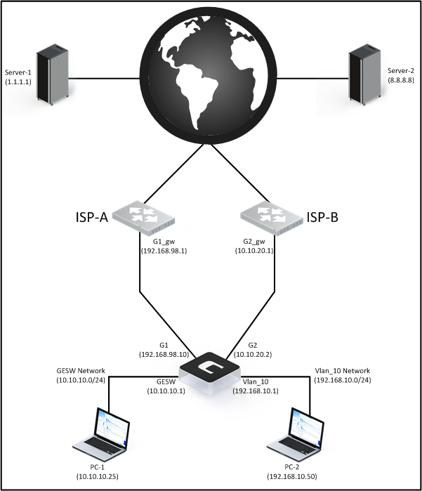
Note: This example will assume that all traffic is outgoing, meaning that it is initiated from behind the firewall to a server/host out on the Internet. This will keep the setup as simple as possible.
If we have a look at the initial routes and IP rule set entries in the firewall configuration before we add our secondary ISP, they might look like this:
2.1 Routing Table:
Flags  Network            Iface          Gateway         Local IP        Metric
------ ------------------ -------------- --------------- --------------- ------
       192.168.98.0/24    G1                                             100
       10.10.10.0/24      GESW                                           100
       192.168.10.0/24    Vlan_10                                        100
       172.16.10.0/24     IKEv2_Tunnel                                   100
       0.0.0.0/0          G1             192.168.98.1                    100
2.2 IP Rule Set:
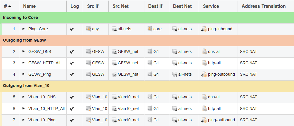
We can see that both the routing and IP rule set are currently configured to use the primary ISP on the G1 interface. We now want to add a secondary ISP behind the G2 interface.
Note about using private IP addresses: Please note that these examples are based on an internal lab setup. That is the reason why we are using private IP addresses on our external interfaces. In a live environment, this will of course not be the case and public IP addresses would be used on G1 and G2.
3. Requirements
We have three requirements that we need to fulfill in this scenario:
1. The users behind the GESW interface should use ISP-1 to reach the internet.
2. The users behind the Vlan_10 interface should use ISP-2 to reach the internet.
3. GESW and Vlan_10 should not be aware of each other or be able to communicate.
Question: Should I use VR or PBR?
Both VR and PBR have their strengths and weaknesses and it may depend on what the administrator actually wants to do. However, here is a brief list of advantages for each:
- VR is better at segmenting networks without the need for any additional PBR rules or exceptions. Just change the interface membership and you are pretty much done.
- PBR is better at controlling traffic. With PBR rules you can, for instance, make a PBR rule trigger only on a specific IP, port or protocol. An example would be if you want to offload DNS and HTTP/HTTPS or maybe VoIP traffic to a secondary ISP. Then, you would need to use PBR because only PBR can redirect traffic based on service/ports.
Let us start with using the Virtual Routing solution.
4. Solving the problem using Virtual Routing (VR)
Once we have connected the G2 interface to the secondary ISP (ISP-2) and configured the G2 interface with the required IP addresses and networks, it is time to create a secondary routing table.
4.1. Creating the secondary routing table. 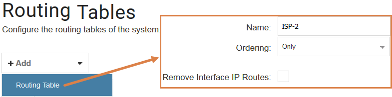
The ordering of the routing table here is quite important but it can also come down to personal preference. There are three choices regarding the Ordering property:
Default
The default behavior is to first look up the route in the main table. If no matching route is
found, or a default route is found (a route with the destination all-nets), a lookup for a
matching route in the alternate table is performed. If no match is found in the alternate
table then the default route in the main table will be used.
First
This behavior is to first look up the connection’s route in the alternate table. If no matching
route is found there then the main table is used for the lookup. The default all-nets route
will be counted as a match in the alternate table if it is found there.
Only
This option ignores the existence of any other table except the alternate table so that is the
only one used for the lookup. One application of this option is to give the administrator a way to dedicate a single routing
table to one set of interfaces. This option is typically used when creating virtual systems
since it can dedicate a routing table to a set of interfaces.
These options can be quite confusing, which one to use depends on the person configuring the system. As mentioned earlier, there can be several ways to accomplish the same result and which method to use can come down to personal preference.
One method that could be considered easier to understand is if we use the option “Only”. The principle for an “Only” routing table is that any packet that ends up in the routing table, stays in that routing table. So you need to make sure that all the required routes exist in the routing table if a packet ends up using the table.
In scenarios where we want to isolate interfaces using VR and to avoid intercommunication between internal networks, the Only option is required. For example, where we have a scenario where the same network is used behind multiple interfaces. VR and “Only” need to be used to avoid routing problems and communication spillover between similar networks. Basically, it is a way to build traffic-proof bulkheads between different internal networks.
4.2. Interface routing table memberships
Since the requirement is that G2 and Vlan_10 should be paired, we make these two interfaces a specific member of the routing table ISP-2, as shown in the WebUI screenshot below for the G2 interface.
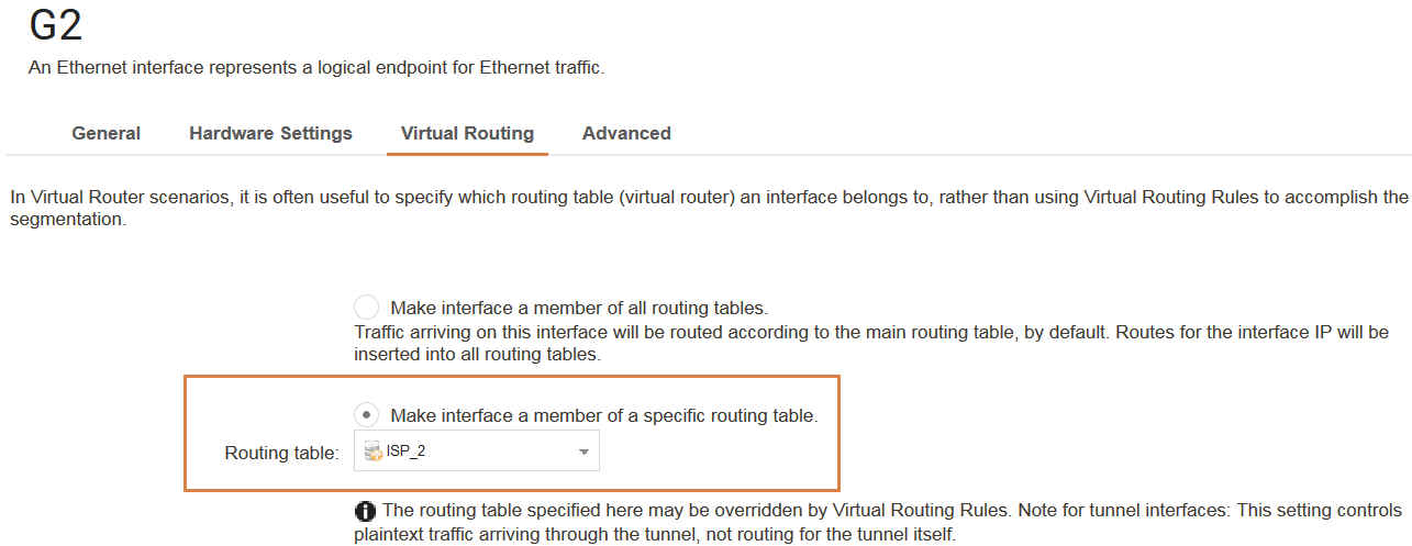
Next, we repeat the same operation for the Vlan_10 interface. Once this is done, we need to make sure that the correct routes are in this routing table. Since G2 should be configured similarly to G1 in terms of network and ISP gateway, the ISP-2 routing table should look something like this:
Routing table: ISP_2


Flags  Network              Iface             Gateway          Local IP   Metric
------ ------------------ -------------- --------------- ---------------  ------
          10.10.20.0/24    G2                                             100
          192.168.10.0/24  Vlan_10                                        100
          0.0.0.0/0        G2                  10.10.20.1                 100
As we can see, there is no references to the G1 or GESW interfaces in this routing table. And since both G2 and Vlan_10 are specific members of this routing table, it means that any other traffic that arrives in this routing table will be dropped by the firewall.
4.3. Modifying the IP rule set to use the secondary ISP
The last thing we need to do is change the IP rule set. Since rule set entries will initially assume the G1 interface for reaching the Internet, we need to change them to use the G2 interface instead (as that is the connection to the ISP to be used for traffic from the Vlan_10 interface).
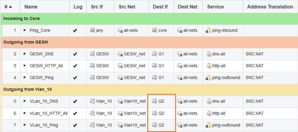
Now, if a packet is sent from a client behind Vlan_10, the firewall will pick up the packet and notice that the interface is part of the ISP-2 routing table. The firewall will then look in the ISP-2 routing table to verify that the source interface is Vlan_10 and then try to find a matching route for the destination network.
4.4. Testing the rules and routes using ping simulations
If we, as an example, try to ping a host on the Internet using a ping simulation in the CLI, it might look like this:
E5:/> ping 8.8.8.8 -srcif=Vlan_10 -srcip=192.168.10.50 -verbose
Rule and routing information for ping:
PBR selected by rule "iface_member_ISP_2" - PBR table "ISP_2"
allowed by rule "Vlan_10_Ping"


Sending 1 4-byte ICMP ping to 8.8.8.8 from 10.10.20.2
sent via route "0.0.0.0/0 via G2, gw 10.10.20.1" in PBR table "ISP_2"


Ping Results: Sent: 1, Received:1, Avg RTT: 10.0 ms
As we can see, the secondary ISP interface (G2) is correctly used to reach the Internet.
And as a final check to make sure that Vlan_10 is unable to reach the network behind GESW, we can run a second ping simulation to verify this:
E5:/> ping 10.10.10.25 -srcif=Vlan_10 -srcip=192.168.10.50 -verbose
Rule and routing information for ping:
PBR selected by rule "iface_member_ISP_2" - PBR table "ISP_2"
allowed by rule "Vlan_10_Ping"


Sending 1 4-byte ICMP ping to 10.10.10.25 from 10.10.20.2
sent via route "0.0.0.0/0 via G2, gw 10.10.20.1" in PBR table "ISP_2"


Ping Results: Sent: 1, Received:0, Loss: 100%
Some may initially think that the above simulation output looks strange as it seems to allow the connection attempt, but the output is correct. The firewall is attempting to find the host with IP 10.10.10.25 and performs a route lookup for this destination IP in the ISP-2 routing table, and the matching route will be the all-nets route towards the Internet. We should also have an IP rule set entry that allows pings towards the Internet so this will allow the traffic to be forwarded to the ISP-2 gateway IP address.
Note: In a real-life scenario, the private IP 10.10.10.25 would be a public IP address, otherwise the ISP router will most likely drop the traffic.
All the requirements have now been met using Virtual Routing.
5. Solving the problem using Policy Based Routing (PBR)
Before we start we will again go back to using the base routing and rule set setup shown in section 2.1. and 2.2. Once we have connected the G2 interface to the secondary ISP (ISP-2) and configured the G2 interface with the required IP addresses and networks, it is now time to create the secondary routing table.
5.1. Creating the secondary routing table.
We will be using the exactly same routing ordering as when solving the scenario using VR.
For information and details about the different route orderings please see section 4.1.
We will again be using ordering “Only” on our new routing table. The reason why we want to use “Only” is mainly due to personal preference but it is also easier to understand. When “Only” is used, one of the basic principles is that when traffic arrives in this routing table, it stays in this routing table.
This can be very useful as we then know that both the source and destination IP addresses must exist in this routing table in order for traffic to flow correctly.
Since we are not using VR, we do not change any settings on the interfaces. All interfaces will be a member of all routing tables (the default setting). But we will need PBR rules in order to make traffic use this routing table instead of the default <Main> routing table for Internet access.
5.2. Creating the needed routes in the secondary routing table.
The routes will be the same as when we solved it using the VR method and it will look like this in <Main> and our <ISP_2> routing table when we are done:
Routing table <Main>
E5:/> routes
Flags  Network              Iface              Gateway         Local IP  Metric
------ ------------------ -------------- --------------- --------------- ------
          192.168.98.0/24   G1                                            100
          10.10.10.0/24     GESW                                          100
          192.168.10.0/24   Vlan_10                                       100
          0.0.0.0/0         G1                192.168.98.1                100
Routing table <ISP_2>
E5:/> routes ISP_2
Routing table: ISP_2
Flags  Network             Iface              Gateway         Local IP   Metric
------ ------------------ -------------- --------------- --------------- ------
       10.10.20.0/24       G2                                            100
       192.168.10.0/24     Vlan_10                                       100
       0.0.0.0/0           G2                10.10.20.1                  100
Note: Removing the routes from <main> and adding them to the <ISP_2> routing table is done by removing the auto added routes option on the G2 and Vlan_10 interfaces then manually adding/creating them in the secondary routing table. Since we do not want to change the routing table membership on interface G2 and Vlan_10, we must first remove them from <main> and manually created them in <ISP_2>.
When we are done we will end up with three routes in the <ISP_2> routing table. Two for the external (G2) interface towards the Internet and one for the local / internal network (Vlan_10).
5.3. Creating the needed Policy Based Routing rule.
Now, when the route setup is completed, we must create a PBR rule that tells the firewall in what situations this secondary routing table (ISP_2) should be used. Since we want Internet access for our Vlan_10 interface to use ISP2 behind the G2 interface, we need to create a PBR rule that looks like this: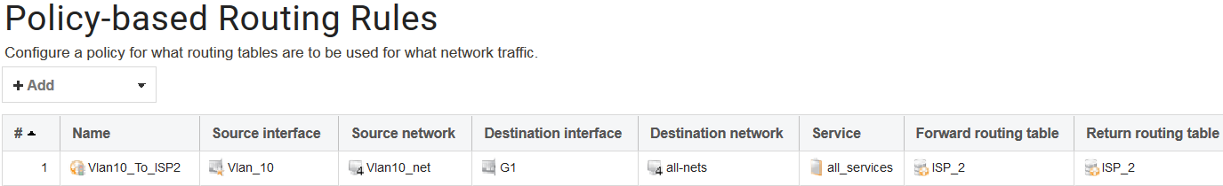
The PBR rule can be interpreted as something like this:
“If traffic is received on the “Vlan_10” interface and is part of the “Vlan10_net” network and is heading towards the G1 interface, no matter the destination network and no matter which port or protocol is used, insert the traffic into the “ISP_2” routing table for further processing.”.
One thing that stands out here in the PBR rule is that the destination interface is G1 and not G2. The reason for this is because the firewall will perform a route lookup for the destination IP in the <main> routing table. Therefore, the outgoing PBR rules destination interface MUST be based on the route lookup for the destination IP in the <main> routing table.
Since the all-nets route in the <main> routing table towards the Internet points to G1, the PBR rule’s destination network must also be G1 in order to override it.
Warning: PBR rules are extremely powerful as they will be consulted first before any route lookup. You can override pretty much any route lookup using a PBR rule.
5.4. Modifying the IP policy rules to use the secondary ISP
The last thing we need to change is the IP policy rules. Since they are currently pointing towards the G1 interface in order to reach the internet we need to change them to point towards the G2 interface instead as that is the primary ISP to be used for users behind the Vlan_10 interface due to the PBR rule “override”.
5.5. Testing the rules and routes using ping simulations.
Similar do our VR example we first evaluate that Internet access seems to be working by sending a ping to a host on the Internet and simulating that it is generated and received on/from the Vlan_10 interface.
E5:/> ping 8.8.8.8 -srcif=Vlan_10 -srcip=192.168.10.50 -verbose
Rule and routing information for ping:
PBR selected by rule "Vlan10_To_ISP2" - PBR table "ISP_2"
allowed by rule "Vlan_10_Ping"


Sending 1 4-byte ICMP ping to 8.8.8.8 from 10.10.20.2
sent via route "0.0.0.0/0 via G2, gw 10.10.20.1" in PBR table "ISP_2"


Ping Results: Sent: 1, Received:1, Avg RTT: 10.0 ms
The simulation looks good. In the output above, we see that the PBR rule triggers and forwards the traffic into the ISP_2 routing table where it performs a new route lookup and finds the destination network (8.8.8.8) for the Internet route on G2.
Next, we will try to verify that Vlan_10 is unable to reach the network behind GESW:
E5:/> ping 10.10.10.25 -srcif=Vlan_10 -srcip=192.168.10.50 -verbose
Rule and routing information for ping:
DROPPED by rule "Default_Access_Rule"
This output appears a little strange. The reason for the message is due to routing. The firewall checks that IP address 192.168.10.50 is routed behind the Vlan_10 interface and the check fails. The reason for this failure is because the interface Vlan_10 is a member of all routing tables. This means that the firewall will attempt to find 192.168.10.50 in the <Main> routing table and the only matching route for this network in the <Main> table is the G1 interface. So packets will be dropped if we attempt this, and this is exactly what we want it to do in this scenario. We do not want Vlan_10 to be able to reach the GESW network.
To further visualize the routing issue, let us do a route lookup in the main routing table to make the firewall tell us where it believes 192.168.10.50 is located.
E5:/> route -lookup=192.168.10.50


Looking up 192.168.10.50 in routing table "main":


Matching route: 0.0.0.0/0
Routing table : main
Send via iface: G1
Gateway : 192.168.98.1


Proxy ARP on :
Local IP : (use iface IP in ARP queries)
Metric : 100
Flags :
As we can see, the firewall believes 192.168.10.50 is routed behind G1 and not Vlan_10 and will therefore drop the packet.
Since we do not have any PBR rules that could possibly override this behavior, the packets will be dropped due to the “Default_Access_Rule”. More information about “Default_Access_Rule” can be found in the following FAQ: https://kb.clavister.com/324735778
We can attempt a second ping simulation to try the reverse, to try reach the Vlan_10 network from the GESW interface:
ping 192.168.10.50 -srcip=10.10.10.50 -pbr=ISP_2 -verbose


Sending 1 4-byte ICMP ping to 192.168.10.50 from 10.10.10.50 using PBR table "ISP_2"
... using route "192.168.10.0/24 via Vlan_10, no gw" in PBR table "ISP_2"


Ping Results: Sent: 1, Received:0, Loss: 100%
This output can look a bit confusing as it may actually appear as though it might be working. The reason for this is due to a limitation in the ping simulation. Since –pbr and –srciface cannot be combined, it means that it will not be possible to simulate this fully in another routing table. This means that the packet will be initiated from cOS Core itself and that will always be allowed. Normally this would have been dropped by either the “Default_Access_Rule” or the “Default_Drop_Rule” that triggers if no matching IP rule set entry can be found. So this particular test cannot be simulated but rather needs to be tested using real traffic.
All requirements have now been met using PBR rules.
Question: What about incoming traffic in the PBR scenario?
Incoming traffic can be a bit more difficult as the PBR rule needed for it depends on what the administrator wants to do. To consider a simple example, we might want to allow incoming traffic to the interface IP on G2 (ISP2). It could be that we have a webserver behind Vlan_10 and we want to address translate (SAT) traffic going to G2_ip to the webserver’s private IP.
To address this requirement, we first need to setup an incoming PBR rule as shown in the WebUI screenshot below:

Then we need an IP Policy in the IP rule set that allows the traffic and forwards it to the webserver behind Vlan_10, as shown in this screenshot: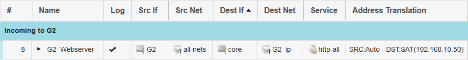
Lastly, we can test the rule and routes using a ping command simulation which should look something like this:
E5:/> ping 10.10.20.2 -srcif=G2 -srcip=8.8.8.8 -tcp -port=443 -verbose
Rule and routing information for ping:
TCP: 8.8.8.8:14494 -> 10.10.20.2:443 PBR selected by rule "ISP2_To_Vlan10" - PBR table "ISP_2"
TCP: 8.8.8.8:14494 -> 10.10.20.2:443 allowed by rule "G2_Webserver"


Sending 0-byte TCP ping to 192.168.10.50:443 from 8.8.8.8:14494
sent via route "192.168.10.0/24 via Vlan_10, no gw" in PBR table "ISP_2"
In order to evaluate if this ping simulation looks good or not (the webserver in this case is not present, as we only want the test to verify that the rule and routes seem to be correct) we look at the following output in the ping simulation:
1. The correct PBR rule triggers and inserts it into the ISP_2 routing table.
2. The correct IP Policy triggers (G2_Webserver).
3. Since the IP Policy “G2_Webserver” is a policy that performs address translation, we see that it forwards the packet further to 192.168.10.50 which is then sent out on the Vlan_10 interface, again using the ISP_2 routing table.
Based on the ping simulation output, everything looks like it is working as expected and the configuration is ready to be used with live traffic.
Related articles
21 Oct, 2022 core arp routing
12 Apr, 2023 core proxyarp arp ipsec routing
28 Mar, 2023 ikev2 windows vpn routing splittunneling
22 Mar, 2021 core ipsec routing
11 Dec, 2025 core routing ospf ipsec
17 Jun, 2021 core ipsec routing
30 Nov, 2022 core routing
1 Jun, 2022 core routing management
25 Nov, 2022 core routing bgp
25 Sep, 2025 core routing pbr
15 Dec, 2022 core routing ospf
12 Jan, 2026 core howto routing redundancy
7 Nov, 2022 core arp log routing
6 Apr, 2023 core ripv2 routing
17 Mar, 2023 core routing rules ping icmp cli
27 Jan, 2021 core stateless routing brokenlink
13 Feb, 2023 ipsec core routing failover
18 Apr, 2023 core routing transparentmode proxyarp