Objectives with this article
This article will describe the basics of troubleshooting TCP MTU/MSS related issues, it will also describe how to configure Wireshark to show the information we need in order to troubleshoot. We will discuss how we can determine that the network issue is related to MTU/MSS based on the Sequence number, Next Sequence number and the Acknowledgement number in a packet capture.
The characteristics for a MTU/MSS related issue can be many things but most often it results in dropped connections and/or bad network performance.
Note that all example packet captures found in this article can be downloaded in a single compressed RAR file here: MTU.rar
For more information about Wireshark and how to download it, please visit the official site at : https://www.wireshark.org/
Configuring Wireshark to show the information we need
Wireshark does not show Sequence number, Next Sequence number and the Acknowledgement number by default as columns. First, we need to add them, the simplest way to do that is start a packet capture and look for a TCP packet as shown below:
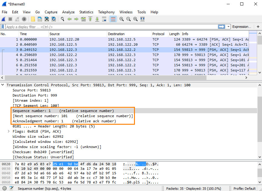
Note that Next Sequence Number has brackets [] around it. That is because this is a number “made up” by Wireshark that is based on the packet length and the sequence numbers. We will discuss how that works later.
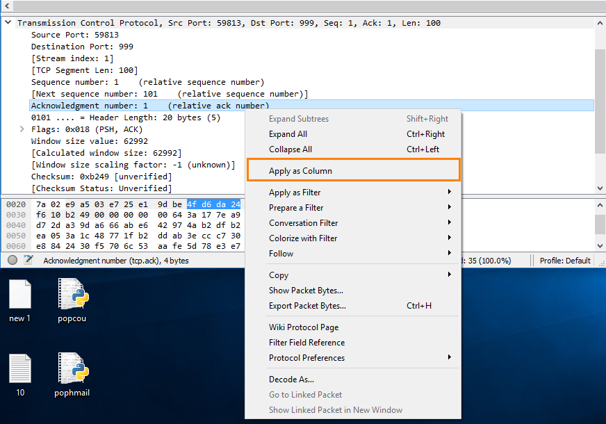
To apply the parameters as columns we just have to right click on the field and choose “Apply as column” for Sequence number, Next Sequence number and the Acknowledgement number.
We should now have the following columns in Wireshark:
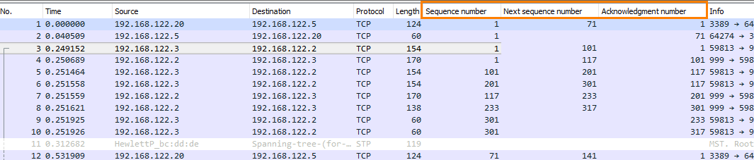
We recommend to have them in the same order as the image above since it will be easier to read. It is also possible to rename the columns to something shorter for example SEQ, Next SEQ and ACK to make it even easier to read.
There is one item that we may consider changing and that is to disable “Relative Sequence Numbers” in Wireshark for the TCP protocol. This is totally up to the administrator and how they prefer to read it. By disabling the option we will see the real/absolute SEQ, Next SEQ and ACK numbers which can be a bit cumbersome to read. By having it enabled the relative SEQ and ACK numbers will be shown, meaning that all SEQ and ACK numbers always start at 0 for the first packet seen in each conversation. You can read more about the setting at this link to the Wireshark Wiki: https://wiki.wireshark.org/TCP_Relative … ce_Numbers
We will assume the setting is enabled in this article.
An explanation of Sequence numbers, MSS and MTU
We will now try to explain how SEQ numbers MSS and MTU are directly related to each other and we will also look at an example from when it works. We will also look briefly at Selective Acknowledgement (SACK) which also can be good to know when troubleshooting TCP problems.
What is MTU?
MTU stands for Maximum Transmission Unit meaning the size on the largest network layer protocol data unit that can be communicated in a single network transaction. Depending on if we included the Ethernet frame or not the standard is 1500 bytes (Wireshark will show 1514 bytes as length since the Ethernet frame is included) for a TCP packet that would be the IP Header (20 bytes) + TCP Header (20 bytes) + TCP segment length (1460 bytes).
What is TCP MSS?
MSS stands for Maximum Segment Size which specifies the largest amount of data that a device can receive in a single TCP segment. The TCP MSS does not include the IP header or the TCP header. MSS is negotiated in the three way handshake between the client and the server at the beginning of a TCP connection.
What is Sequence numbers?
Sequence number is used to keep track of the data sent in a TCP communication. Both the server and the client will have different SEQ numbers and the SEQ numbers will be based on the length of the TCP segment in the packet. If you have “Relative sequence numbers” enabled in Wireshark each conversation will always start at 0. But in real the SEQ number the conversation could start with any number between 0 and 4,294,967,295.
Working example (The packets are captured on the client): 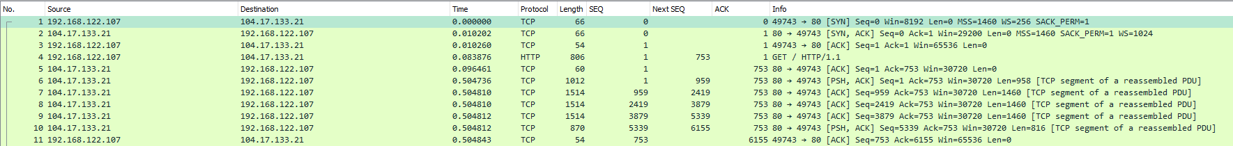
Packet #1
Client sends SYN to server, since this is the first packet in the conversation the relative Sequence number will be 0. You can also see that the client has the MSS set to 1460. The Acknowledgement number is set to 0 since there is no data to ACK.
Packet #2
Server sends SYN/ACK back to the client; since this is the first packet the server sends it will also have the relative Sequence number of 0. The MSS is also set 1460 by the server, meaning that MSS that will be use in this conversation is 1460 bytes. (The MSS used will be the lowest MSS set by either side) The Acknowledgement number is 1 to indicate the receipt of the clients SYN in packet #1.
Packet #3
Client now send the ACK to complete the three way handshake. The Sequence number is increased by one since the client previously sent a SYN packet. The Acknowledgement number is also increased by one to indicate that the client has received the SYN from the server.
Packet #4
The client now sends the HTTP GET, this is the first packet that actually contains any payload. The Sequence number will stay at one since the client has not transmitted any data since the last packet in the stream. The Acknowledgement number will also stay at one since the client has not received any data yet from the server.
The interesting part here is the “Next Sequence number” which is set to 753 and why is that? Next sequence number is based on the TCP segment length and the Sequence number of the packet. In this case the payload of the TCP packet is 752 bytes (806 – IP header(20) – TCP Header(20) – Ethernet frame(14) = 752)
This is also visible in Wireshark if you look at the TCP Header:
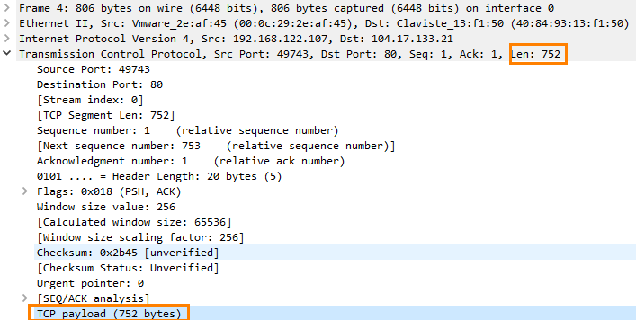
The next sequence number will therefore be Sequence number (1) + TCP segment length (752) = 753. We now know that next packet that the client will send will have the relative Sequence number of 753.
Packet #5
The server now ACKs the HTTP GET, still using the Sequence number 1 since it has not transmitted any payload yet but it has increased the Acknowledgement number to 753, meaning that the server has received 753 bytes of data so far.
Packet #6
The server now transmits the HTTP OK response to the HTTP GET sent in Packet #4. This packet now has the Sequence number of 1 and it still has the same Acknowledgement number 753 since the client has not sent any more data so there is nothing new to Acknowledge.
The interesting part here is that the packet has the Next Sequence number of 959, this means that the next packet the server will send is going to have the Sequence number 959. As mentioned earlier (packet 4) we know this or rather Wireshark knows this because Next Sequence Number is calculated from the current Sequence number + the TCP segment length in this case 1 + 958 = 959.
Some may also notice that this packet has the PSH flag set. The PSH flag in the TCP header informs the receiving host that the data should be pushed up to the receiving application immediately. The PSH flag is beyond the scope of this article and can be ignored for now.
Packet #7 - Packet #10
The server now starts to send the actual HTTP data to the client. The Acknowledgment numbers will still be 753 on all packets that the server sends since the client has not sent any more data so there is nothing new to Acknowledge.
The 7th packet has the sequence number 959 as we previously calculated in packet #6. The 7th packet has the TCP length 1460 so this means that the next packet will have Sequence Number 2419. 1460 is the MSS of this connection; this was agreed upon in the three way handshake.
Same goes for packet #8 and #9 both has 1460 as TCP length meaning that the Sequence number will increase by 1460 after every packet. Simply illustrated:
Packet 7 (SEQ 959) - > Packet 8 (SEQ 2419) -> Packet 9 (SEQ 3879) -> Packet 10 (SEQ 5339)
Packet number 10 is the last packet that the server sends in this example this packet has the TCP length 816 meaning next packet that the server sends will have the sequence number 6155.
Packet #11
The Client now Acknowledge the packet that the server has sent, the sequence number of this packet has now increased to 753 as we mentioned in Packet #4. The Acknowledgment Number has now increased to 6155 this means that the client has received 6155 bytes of data from the server. This also means that the client has received all data between 0 and 6155 bytes.
Summary
As we can see in this example nothing goes wrong both server and client receive all packets. We can also see that the sequence number is directly connected to the TCP length, after each packet the sequence number is increased by the TCP length of the packet. Both sides of the connection have their own unique SEQ number and the MSS is agreed upon in the three-way handshake.
How can I see that the issue is related to MSS/MTU?
We will now go through an example where it doesn’t work and try to analyze why the connection has issues. We will also have a look at Selective Acknowledgement (SACK) that sometimes can help you to trouble shoot MSS/MTU related issues.
Below Capture taken from the WAN interface of the Clavister and this is a HTTPS connection.
Packet #1 - #3
Same as in the previous example, Three-way handshake is completed. The agreed MSS is 1460 bytes and also SACK is permitted by the server and the client (SACK_PERM=1). SACK stands for Selective Acknowledgements; if packets are lost the data receiver can inform the sender by sending a Duplicate ACK and appending a TCP option containing a range of noncontiguous data received. This allows for more efficient TCP transmission in packet loss scenarios. The data sender then only needs to retransmit the packets that the receiver did not get, instead of all packets.
Packet #4
The client now sends the Client Hello packet initiating the TLS handshake. The ACK number is still 1 since there is nothing new to Acknowledge and Next SEQ will be 132 since the packet length is 131 bytes. The Client now waits for the Server hello.
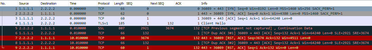
Packet #5
Now something goes wrong, the server sends a packet with Sequence number 2921, why? The sequence number should be 1 since the server has not transmitted any data yet.
Since we know that the sequence number should be 1 on this packet we can also calculate that we are missing 2920 bytes of data in this conversation (2921 - 1 = 2920).
Next packet that the server sends will have sequence number 3674.
Packet #6
And here is where SACK comes into play, client now sends the Duplicate ACK to tell the server “Hey, I did not get all packets but I got the data between SEQ number 2921 and 3674”.
Sequence number will still be 132 as we stated in Packet #4 but the Acknowledgement number will not increase since we have not received data between SEQ number 1 and 2921.
The Acknowledgment for the data between 2921 and 3674 will now instead be in the SACK option part of the TCP packet:
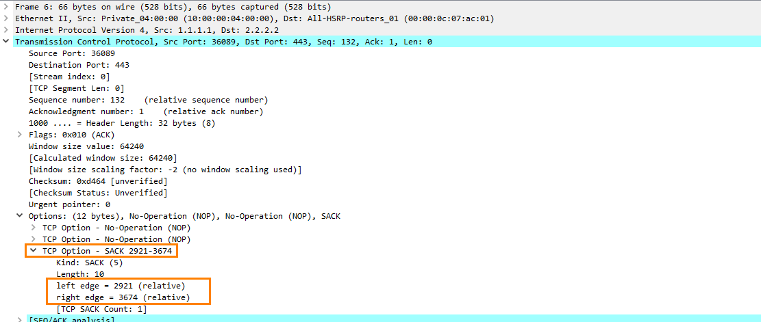
This will tell the server to retransmit the data between 1 - 2921 but not the data between 2921 – 3674
Packet #7 - #9
The server now sends a RST to the client after 10 seconds and closes the connection.
Summary
Here we have an example of when something goes wrong, it seems that we are missing some data. The client sends the “Client Hello” to initiate the TLS handshake but it never receives the response. Judging from Sequence numbers we are missing the data between SEQ 1 and SEQ 2921 so 2920 bytes of data is lost (2921 – 1 = 2920). Another thing that we can assume based on the MSS agreed upon in the three-way handshake (1460) is that the data we lost is most likely two “full size” TCP segments 2920/2 = 1460.
The conclusion we can draw from this is that most likely the MTU is lowered somewhere along the way causing the packets to be dropped. This is only an assumption since we cannot say for sure that this is the case since we have not seen the packet captures on the server side. But all evidence points towards that at least.
Slow internet speed
Even though packets are dropped TCP should be able to “solve” or workaround the problem by retransmitting data in smaller packets, here is an example on how it works:
![]()
Packet #1 - #3
Three-way handshake completed, the agreed MSS is 1460.
Packet #4
Client now sends the HTTP GET, Next SEQ will be 1440 since the TCP length is 1439. The client is now waiting for the server to acknowledge the packet.
Packet #5
Client now retransmits the packet since there was no ACK sent back from the server for 310ms. Next SEQ is still 1440 since this is a retransmission of Packet #4.
Packet #6
Client waits another 600ms and tries to retransmit the packet once again. Next SEQ is still 1440.
Packet #7
Still there is no answer from the server after almost 2 seconds. Client now retransmits the packet again but this time the packet is smaller, the packet has the TCP length 536 bytes. Why 536 bytes?
Ok so first 536 is only the TCP segment length, if we add the IP header and the TCP header we get 536 + 20 + 20 = 576 (Wireshark will say 590 since the Ethernet frame is included) which is the smallest datagram size that any host must be prepared to accept.
The next SEQ number will now be 537 instead of 1440 since the client will retransmit the packet in smaller chunks.
Packet #8
Now we finally get an answer from the server, the server now Acknowledge Packet #7. Acknowledgement number is now 537 since the server has not received the data between SEQ 537 and SEQ 1440.
Packet #9
The Client now retransmits another packet that contains 536 bytes of data. This packet now has Next SEQ 1073.
Packet #10
Client now retransmits the last data in a 367 bytes TCP segment. The client has now spread out the HTTP Get over three different packets, packet #7, packet #9 and packet #10. The total TCP data is still 1439 bytes (536 + 536 + 367 = 1439).
Packet #11 and Packet #12
The server now Acknowledge the two last packets sent by the server. All packets sent by the client has now arrived on the server.
Summary:
Even though there is a MTU/MSS problem in this network the connection was not dropped. However the packets were transmitted in a very inefficient way. By retransmitting the packet in smaller chunks we have increased the round trip time by about 2 seconds we have also doubled the number of packets that is sent in this connection.
How to configure the Clavister to avoid these problems
There are basically three things you can do in order to improve the situation.
- Modify the MTU on the involved interfaces
- Modify the TCP MSS Max advanced setting
- Enable Path MTU Discovery on the service
How to know what to do? This is very situational and it depends on the Network topology. But we will try to break it down a bit.
Modify the MTU on the involved interfaces
First of what should we change the MTU to and which interface should we change it on? The easiest way to figure this out is with ping and the length parameter. Here is an example from Windows CMD:
ping 8.8.8.8 –l 1372This will send an ICMP packet that contains 1372 bytes of data to 8.8.8.8. Let’s say that 1372 is the largest amount of data that you can send and still get an answer, this means that the MTU is 1400. Remember we need to add the IP header and now we also need to add the ICMP header, 1372 bytes + 20 bytes + 8 bytes = 1400 bytes.
Now on which interface should we change the MTU, let’s say that we have a simple setup like this:
Clients ---(LAN)Firewall(WAN)--- Internet
TCP MSS will automatically be “clamped” to the lowest MTU of the involved interfaces. If you have two interfaces Lan(1400 MTU) and Wan(1500 MTU) the TCP MSS used will be 1360. It will be up to the administrator to decide on which interface you want to modify the MTU. Let’s say that we also have a DMZ interface where internal resources resides that the LAN clients are using. If so it might not be preferable to lower the MTU on the Lan interface since we will then also use the lower MSS when communicating between the LAN and DMZ interface.
Modify the TCP MSS Max advanced setting
As mentioned changing the MTU will affect all traffic on that traffic including UDP traffic. Sometimes it could be beneficial to just change the TCP MSS Max setting. This will only affect TCP traffic but it’s however a global setting. Meaning, all interfaces will be affected (Excluding VPN interfaces). As mentioned this is very situational, there could be situations where only TCP traffic are affected.
The TCP MSS Max setting can be found under System -> Advanced Settings -> TCP Settings in the WebUI. Default value is 1460 bytes and as mentioned this is a global setting and will affect all TCP traffic passing through the firewall.
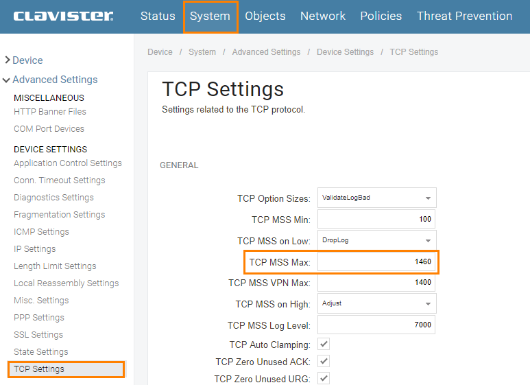
This cannot be tested with ICMP since it only changes the MSS of TCP, in this case you have to look at packet captures. For example decrease the value by 10 to 1450 and try to visit any HTTP or HTTPS site, can a full size segment reach the server or can the server send a full size segment back. If not decrees TCP MSS Max even more.
Enable Path MTU Discovery on the service
This will enable the possibility for the Clients to modify the MTU them self without the need for an administrator to do anything other than activating it on the firewall. But it does however require that all nodes between the Client and the Server to support Path MTU Discovery and that is not always the case.
PMTUD works by using the Don’t Fragment (DF) bit of the IP header and a subcode of the ICMP Destination Unreachable message, “Fragmentation Needed”.
Here is an example on how it works:
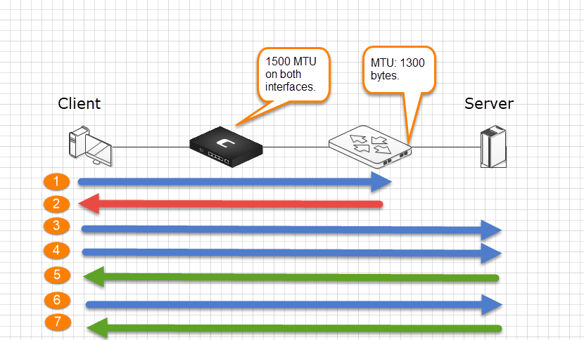
- Client sends a 1500 byte TCP packet.
- Router sends a ICMP error “Fragment to 1300 bytes”
- Client now sends a 1300 byte TCP fragment.
- Client then sends the rest of 1500 bytes of data, 200 bytes.
- Server ACKs the data.
- Client now send 1300 bytes of data.
- Server ACKs the data.
Now the Path MTU has been learned and the client can cache this value and future data for the destination is sent with the appropriate size.
In the Clavister Path MTU Discovery is enabled on a Service base, it’s not a “global” setting that affect the whole system. In order to activate it we need to enable two settings on the service: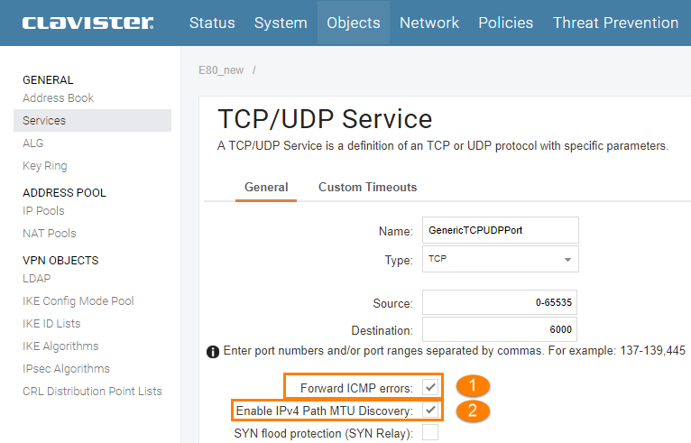
- “Forward ICMP Errors” – Allows ICMP error for active connections to be forwarded through the system.
- “Enable IPv4 Path MTU Discovery” – Allows communicating endpoints to negotiate optimal packet sizes. This prevents fragmentation by network equipment between the endpoints. Path MTU Discovery relies on ICMP message forwarding so ICMP forwarding must also be enabled.
Related articles
17 Sep, 2025 stream wireshark
8 Sep, 2020 snmp core wireshark
7 Sep, 2022 core cli pcap netwall pcapdump
7 Dec, 2022 pcapdump log cli core logsnoop